I'm working on the user interface for my MIDI Thru Box, and will
need some number of buttons on the front panel. I'm not sure how
many yet, but it'll be at least four and maybe as many as eight.
The thing is, I didn't want to use up eight IO ports on the
Netduino just for handling buttons. A button is essentially a 1 bit
value; it's either on or off.
For the other installments in this series, see these links.
Because they are simple on/off or 0/1 values, you can use a
shift register to pack a number of them into a single bit of data
(8 bit byte, for example) using SPI. The concept is conceptually
the same as using bit masking in desktop applications where you
could pack 8 boolean values into a single byte. I knew the
electronics involved here wouldn't require blazing any new trails,
so I was especially happy to see what
Stefan had created on the Netduino forums.
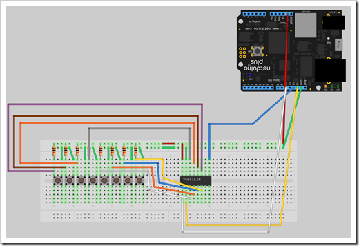
Schematic
I created a quick and ugly schematic/diagram of the setup using
Fritzing. I'm using a
Netduino, not a Netduino Plus, but the pin-out is the same.
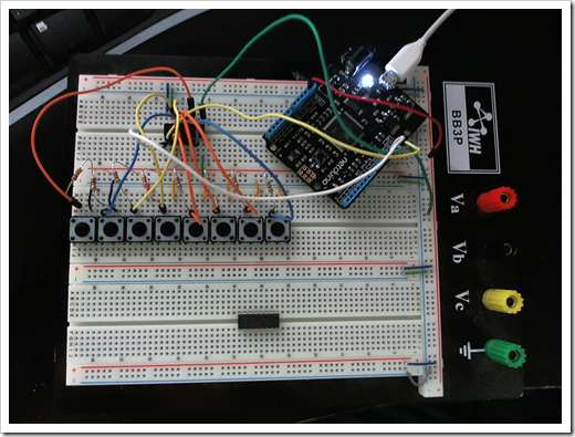
Here's a photo of the actual setup. The wire colors do not match
those in the diagram. The extra chip at the bottom is a 74HC595N
for the second part of this project.
Parts Used
- (1) Original Netduino
- (1) 74HC165N Parallel to Serial Shift Register (Mouser
771-74HC165N)
- (8) 1/8 watt 10k Resistors (the value isn't super important,
just don't go really high or really low)
- (8) SPST 12mm x 12mm SPST switches (Mouser
612-TL1100)
- Prototyping board
How it Works
The 74HC165N
is a common 8-bit parallel to serial shift register. I had a tube
of them in my cabinet just waiting for a project like this. From
the data sheet:
The 74HC165; 74HCT165 are high-speed Si-gate CMOS devices that
comply with
JEDEC standard no. 7A. They are pin compatible with Low-power
Schottky TTL (LSTTL).
The 74HC165; 74HCT165 are 8-bit parallel-load or serial-in shift
registers with
complementary serial outputs (Q7 and Q7) available from the last
stage. When the
parallel load (PL) input is LOW, parallel data from the D0 to D7
inputs are loaded into the
register asynchronously.
When PL is HIGH, data enters the register serially at the DS
input and shifts one place to
the right (Q0 ® Q1 ® Q2, etc.) with each positive-going clock
transition. This feature
allows parallel-to-serial converter expansion by tying the Q7
output to the DS input of the
succeeding stage.
The clock input is a gated-OR structure which allows one input
to be used as an active
LOW clock enable (CE) input. The pin assignment for the CP and CE
inputs is arbitrary
and can be reversed for layout convenience. The LOW-to-HIGH
transition of input CE
should only take place while CP HIGH for predictable operation.
Either the CP or the CE
should be HIGH before the LOW-to-HIGH transition of PL to prevent
shifting the data
when PL is activated.
The Netduino uses the SPI bus to speak with the chip to enable
it to pack the data from all eight buttons into a single message.
The 10k pull-up resistors attached to the signal side of each
button are required to eliminate the random noise you get
otherwise. When a button is open, the current travels through the
pull-up resistor to the +3.3v side. When the button is closed, the
easier path for the signal is right to ground, since there's no
resistor there. Therefore, when a button is open, it has a value of
"1", when it is closed, it has a value of "0". This is opposite of
what we think in computer science, but is very common in
electronics.
| Button number |
7 |
6 |
5 |
4 |
3 |
2 |
1 |
0 |
Total |
| Bit Value |
128 |
64 |
32 |
16 |
8 |
4 |
2 |
1 |
|
| No buttons pressed |
1 |
1 |
1 |
1 |
1 |
1 |
1 |
1 |
255 |
| All buttons pressed |
0 |
0 |
0 |
0 |
0 |
0 |
0 |
0 |
0 |
| Buttons 0 and 4 pressed |
1 |
1 |
1 |
0 |
1 |
1 |
1 |
0 |
238 |
| Button 0 pressed |
1 |
1 |
1 |
1 |
1 |
1 |
1 |
0 |
254 |
It's possible I have the numbers reverse from how Stefan's code
and the shift register do the conversion, as I didn't check to see
how he did it. If that's the case, just reverse the button numbers
so they read from 0 to 7 rather 7 to 0. Otherwise it's
identical.
Windows 7 Calculator Can Help
Has it been a while since you had to do calculations like this?
Just hate doing math in your head? If you have Windows 7, just open
up Calc and switch to Programmer mode. You can then do your work in
Binary. For example, here I typed in the values for 0 and 4.
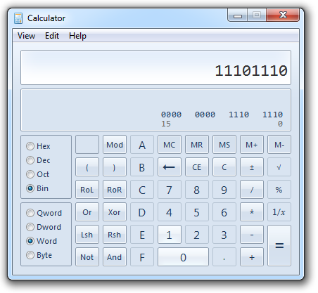
Note that I left it in "Word" mode. I didn't want the high-order
byte treated as a sign bit. There's probably a way to turn that
off, but I didn't see it. Switching to 16 bit accomplishes the same
thing.
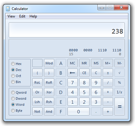
Then I clicked the "Dec" button to convert to decimal, et
voila:
Code
I would not have started and completed this exercise tonight if
I didn't have the nice code from Stefan. That code handles chaining
multiple shift registers together to enable a large number of
buttons on a single SPI bus; pretty nice! I only used a subset of
the code, however. I downloaded his example as posted on the forum,
and modified the main program so it looked like this:
public class Program

{

    public static void Main()

    {

        Ic74HC165Chain ChainIn = new Ic74HC165Chain(SPI_Devices.SPI1, Pins.GPIO_PIN_D10, 1);

        Ic74HC165 IcIn1 = new Ic74HC165(ChainIn, 0);


        InterruptPortShift[] Buttons = new InterruptPortShift[8];

        Buttons[0] = new InterruptPortShift(IcIn1, Ic74HC165.Pins.GPI_PIN_D0, false, Port.ResistorMode.Disabled, Port.InterruptMode.InterruptEdgeBoth);

        Buttons[1] = new InterruptPortShift(IcIn1, Ic74HC165.Pins.GPI_PIN_D1, false, Port.ResistorMode.Disabled, Port.InterruptMode.InterruptEdgeBoth);

        Buttons[2] = new InterruptPortShift(IcIn1, Ic74HC165.Pins.GPI_PIN_D2, false, Port.ResistorMode.Disabled, Port.InterruptMode.InterruptEdgeBoth);

        Buttons[3] = new InterruptPortShift(IcIn1, Ic74HC165.Pins.GPI_PIN_D3, false, Port.ResistorMode.Disabled, Port.InterruptMode.InterruptEdgeBoth);

        Buttons[4] = new InterruptPortShift(IcIn1, Ic74HC165.Pins.GPI_PIN_D4, false, Port.ResistorMode.Disabled, Port.InterruptMode.InterruptEdgeBoth);

        Buttons[5] = new InterruptPortShift(IcIn1, Ic74HC165.Pins.GPI_PIN_D5, false, Port.ResistorMode.Disabled, Port.InterruptMode.InterruptEdgeBoth);

        Buttons[6] = new InterruptPortShift(IcIn1, Ic74HC165.Pins.GPI_PIN_D6, false, Port.ResistorMode.Disabled, Port.InterruptMode.InterruptEdgeBoth);

        Buttons[7] = new InterruptPortShift(IcIn1, Ic74HC165.Pins.GPI_PIN_D7, false, Port.ResistorMode.Disabled, Port.InterruptMode.InterruptEdgeBoth);


        // We need to place an event on each button

        for (var i = 0; i < Buttons.Length; ++i)

        {

            Buttons[i].OnInterrupt += new NativeEventHandler(IcIn1_OnInterrupt);

            Buttons[i].EnableInterrupt();

        }


        // Now let's get the rest done by events

        Thread.Sleep(Timeout.Infinite);

    }


    static void IcIn1_OnInterrupt(uint PinId, uint Value, DateTime Time)

    {

        if (Value == 0) Debug.Print(PinId.ToString());

    }

}
Run it in debug mode and watch the output window as you press
buttons. You should see the button number print out when you press
it.
That's all there is to it. My next step is to wrap up a
variation of this code and put it into a friendly input class
(likely raising separate named events for each button) that I can
then use to drive the UI displayed on a 2x40 LCD. BTW, I plan to
drive that LCD using a shift register as well. More on that
later.
There is no code to download with this post. Visit the forum
post mentioned above to download Stefan's "BitShiftShizzle"
demo.