Today I spent a little time at the drill press in my shed, and
made a huge mess with aluminum and cutting fluid.
Before you read on, here are the other installments in this
series. You may wish to look them over first.
Spotting the Holes
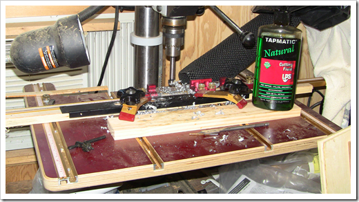
As I mentioned, I went out and made a mess with chips and
cutting fluid. My goal was to quickly cut the rear openings for the
11 MIDI jacks and one power jack. The first step was to mark the
edge of each jack using a hobby knife. The lines will be the
centers of the drill points. I marked using the edges, but offset
the whole back first by 1/2 jack, making it much easier to get
accurate lines using the jack edges as a guide.
I wanted to use my Sherline mill for this, but it doesn't have
quite enough travel to cover the distance from one end to the other
in a single setup, and setting up a CNC operation just to drill
some holes seemed like a lot of planning for just a little work. I
probably will use it for the front panel, if I don't get one
commercially made.
I then drilled pilot holes, as I had expected to use spade bits
when drilling the aluminum. The pilot holes ended up being
unnecessary (and actually in the way) because spade bits are a
horrible choice. When I tried to use a spade bit on the first hole,
it wandered a bunch and instead of cutting through, simply pushed
the metal so it humped up a bit. What I really needed was a 5/8"
hole saw, but what I ended up using was a formerly very sharp 5/8"
forstner bit and a bunch of tapmatic cutting fluid.
Drilling the 5/8" Holes
After completing the holes, I reamed them with a 3/4" hand-held
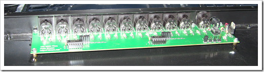
countersink. This removed the burrs and sharp edges. During the
process, I checked the back against the circuit board several
times. Despite that, things were still a little off, but will be
usable. I really wanted to have larger holes (more like 3/4") to
allow a tight fit for the fat plastic cable ends, but couldn't fit
that large a hole in the back.
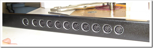
After that was complete, I drilled a hole for the power jack,
and reamed it like the others.
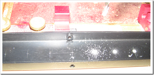
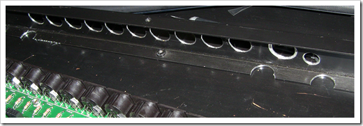
Next, I had to cut some clearance holes for the standoffs. You
can see the half-circle holes here. You can also see how the
workpiece jumped out of the clamps at one point, and the bit
skittered across the bottom. It'll be covered by the board, but not
a great moment in metalworking history :)
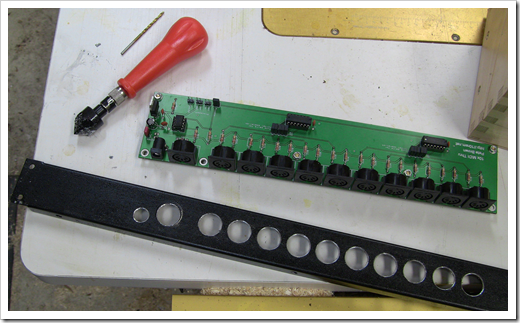
Attaching the Board
The final step was to attach the standoffs to the circuit board,
spread epoxy on them, then hold it in place while the epoxy dries.
Another option would be to drill holes in the bottom of the case
and screw the standoffs in place, but the case top/bottom/sides are
made of steel, and frankly, epoxy is good enough for this.
The end result is decent. The 5/8" holes in the back don't
really leave any room for error, of which I had a fair bit. It
looks like I can get a good connection from each of them, but
they're not all quite centered.
Next Steps
Next I want to wire up a Netduino to this guy and try out some
of the more advanced ideas I had around routing and monitoring.
I'll post about that once I set it up.