The custom circuit board arrived from PCB-POOL while I was away
at MADExpo. Of course, I couldn't wait to put it together. In this
part of the series, I'll assemble the circuit board. For
information on the previous steps, and more photos, please see
these blog posts
Final parts list for the circuit (does not include rack case
hardware or power switch)
Parts for the optional front panel and MCU integration. This
will be the subject of a later post.
- LCD Panel (TBD)
- Netduino or FEZ Panda
- Several momentary buttons and switch caps
Before we get into assembly and soldering, here's a quick recap
of the related steps.
Manufacturing Steps Recap
Below is a recap of the steps required in the manufacture of
this board. For brevity, I only show the top layer of the board in
the WIP photos.
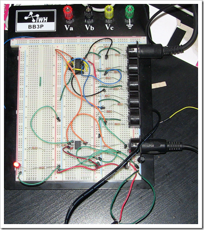
Prototype
Read more about the initial design and prototype in my post here.
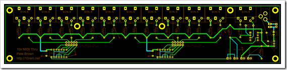
Design
Read more about the design of the board in my post here.
Drilling
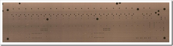
Etching
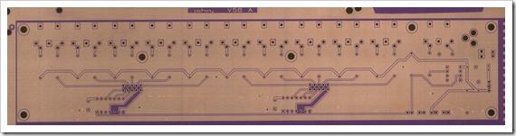
Solder Resist application, Silk Screening, and UV curing
Note how the through holes are still copper-colored at this
point. They haven't yet been coated.
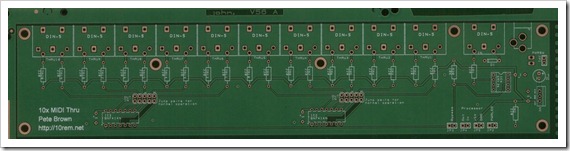
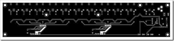
Surface Finishing
You can see both photos in my post here. This is where the coating was applied to
the through holes.
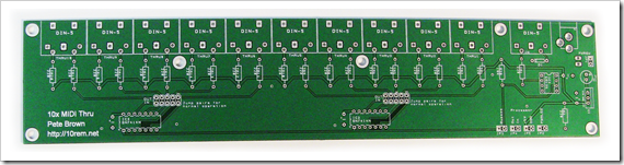
The final board, in my hands
Component Soldering
Now, to soldering. I'm not particularly experienced with
soldering, so it's not super clean. I've also never soldered a
board that had this type of dull (almost white) plating on the
through holes. I believe that's an EU thing to do with RoHS
compliance. Ones in the US typically have shiny plating. I'm
curious to see how that goes. (After soldering, I can say that the
coating did work well - the solder flowed wonderfully.)
Resistors Soldered
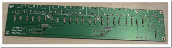
After soldering the resistors, I did a continuity test with my
multimeter to ensure that all the solder joints were good. I
continued this check after each step in the rest of the
soldering.
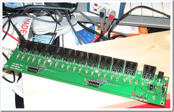
MIDI Jacks Soldered
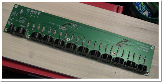
In the second photo, you can see the gap between the MIDI ports.
I definitely could have tightened that up to lose a little width on
the board and provide more stability on the jacks (they should
overlap). In addition, if the jacks were all overlapping as they
should be, I could have potentially just drilled out a large
rectangle in the rear panel, rather than 10 holes, for the thru
ports. I could still do that, but the gaps are ugly, so I
won't.
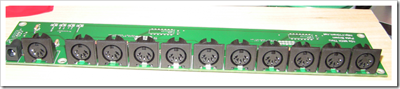
First Jumpers in Place
I have a number of jumpers on the board. Some of them are for
front panel connections like the power LED and the power switch.
Some, like the ones shown in this photo, are to allow a
microcontroller like the Netduino to get in the middle of the
signal.
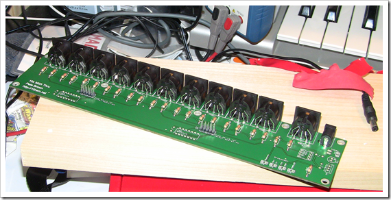
Soldering Complete
All the soldering is complete at this point. All I have to do is
press fit the chips.
Mistakes
I had to have at least one mistake.
When I assembled the board I realized one significant, but
correctable error: I put the large 47uF cap inline between the 9v
power in and the 5v regulator when it should have been a smoothing
cap between the +9v in and ground. I had to remove the cap and do a
little creative jumping to fix it. I didn't want to cut any traces,
so I decided to instead wrap the negative leg of the cap to the
nearest ground point (which also happened to be on a capacitor),
and send the power side back underneath the board to complete the
circuit.
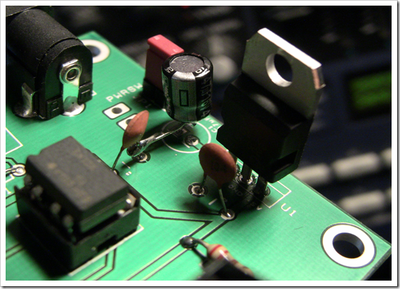
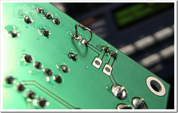
Yes, it's ugly, but it works. In fact, it all works perfectly.
Except for that one hiccup, which I diagnosed by checking the
voltages in the circuit with my multimeter, everything worked fine.
I tested it, and the MIDI signals were coming through
wonderfully.
Next Steps
The next steps are:
- Complete the rack mount case (drill holes in back, drill or
send out the front panel)
- Complete the Netduino and LCD panel add-on
I'm not sure in which order I'll do those. If I end up sending
the panel out to be professionally done, I may simply do that first
and complete the Netduino piece while the panel is being made.
