In this Part 1 post, I'll show how to interface with ATmega
ports and pins to light up LEDs on a board. The follow-up post will
show how to use the timer to actually blink the LED.
Most of the Microcontroller code out in the public is C or
Assembly. I have nothing personal against assembly or C (and may
end up using a little assembly in the future), but I decided I
wanted to write C++, as I like its encapsulation and structure when
compared to straight C.
I've written some other posts about getting started with these
boards and environments. Be sure to check them out:
Disclaimer: I don't have a lot of experience
with the AVR. I'm writing as I'm learning. If you find a mistake
below, please point it out in the comments.
C++ Disclaimer: If code size and execution
speed are your primary concerns, you can certain do a bit better in
C or even more so in assembly. C++ does add some overhead,
especially if you go nuts on the class hierarchies. I've tried to
strike a balance between size, speed, and encapsulation in my own
libraries here, and also to show the differences. If you intend to
write for some of the ATtiny chips with their miniscule 2k or 4k
(sometimes a bit more) program memory, write some macro-oriented C
or better yet, break out that assembler. For the larger chips with
a little more headroom, C++ is a fun way to go, and is my
preference.
Platform Disclaimer: Most of my readers will be
far more productive on the .NET Micro Framework and the Netduino, FEZ Devices, or Gadgeteer. If you're not doing heavy
speed-critical signal processing, you'll probably have more
fun with NETMF and get from zero to application much more
quickly. For people not using C# but who wish to continue
with C/C++ on the AVR specifically, Arduino has most of these types
of things figured out in its rich library. It's not really C++, but
it's a good approach to developing on a subset of the AVR MCUs. If
you're interested more in just getting something done specifically
on the AVR, I recommend looking at that. Finally, if you want to
write C on the metal, Atmel also makes their own AVR library which
helps abstract away the differences between MCUs. I personally
found that confusing to use, with many different ways to accomplish
the same tasks, and a large number of poorly documented APIs to
learn. They were C as well, and without great naming conventions on
their part, it was next to impossible to get a ful picture of
everything available in a particular problem domain. In my case, I
specifically want to learn MCU programming without all that
baggage, so I'm simply coding on the metal but using C++.
Ports and pins
This family of MCUs have 8*4 (32) General Purpose Input/Output
(GPIO) pins. They can all be used for GPIO, but some ports can also
be assigned different functions. Here's are the pin configurations
for the PDIP and the TQFP/QFN/MLF surface mount versions from the
data sheet. (There are other pages covering the tiny VFBGA and
DRQFN versions, in case you wanted super tiny surface mount
versions)
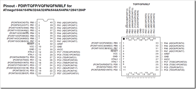
I'm using the PDIP version on the left. On that, you can see,
for example, that pins 14 through 21 (port D) have the transmit
(TXD) and receive (RXD) functions for the USARTs. When you use
those pins for the USART, you can't use them for GPIO, so you need
to be smart about which pins you use for which functions. (I've
been doing a lot with port D and MIDI - more on that in a future
post.) You can also see that the entire family of chips ATmega164A,
ATmega164PA, ATmega324A, ATmega644A, ATmega644PA, ATmega1284, and
ATmega1284P all share the same pin configuration and device layout.
(and yeah, I'll admit that listing them all here was for search
engines <g>). Where they differ is in memory. Here's the
table from the same data sheet.
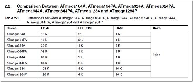
In this post, I'll concentrate on using Port A. As I previously
mentioned, the MCU I'm using is the ATmega1284P, so I have a
whopping (in MCU terms) available program size of 128K. That's as
much total memory as the Commodore 128 computer sitting behind me
on my desk, and that doesn't even count the 16K available RAM and
4k available EEPROM. In a nutshell, here's how that memory is
used:
- Flash: This is the memory used to store your
program code. When you "program" the MCU, this memory is directly
consumed by the instructions for your application.
- EEPROM: This is where you can store persistent
settings, like configuration set by the user of your end
product.
- RAM: Allocated variables, arrays etc. You can
blow through 16K very quickly if you try and do things like you
would on the desktop (like a lookup table of 16 bit values to make
SIN calculations faster), so you need to be smart about that.
Now, back to pins and ports. The ATmega and ATxmega MCUs by
Atmel (and possibly the ATtiny and others - I haven't checked)
group their IO pins into ports. The ATmega1284 has four ports A, B,
C and D, each of which has 8 pins. By grouping this way, a single 8
bit register can contain the digital information for each in in the
port.
So, if you know the base address of Port A's pins data register
is 0x20 (or 0x00, for reasons explained in the data sheet), you can
find out the value of pin 2 using code like this:
#define PINA_ADDRESS 0x20


isHigh = (*PINA_ADDRESS) & 0b00000100;
You can set pin 2 to high using this code, assuming that all the
pins were low before (this actually *toggles* pin 2):
#define PINA_ADDRESS 0x20

(*PINA_ADDRESS) |= 0b00000100;
After you set it, that bit of PINA will be 1 if the pin is high,
and 0 if it is low, regardless of what your code actually sets it
to when toggling.
You can see how using preprocessor defines like that makes the
code easier to read, but still results in a really tiny program. By
default, the AVR libraries include even nicer preprocessor macros
to get to individual pins, but we're not using them here. Of
course, I did oversimplify a little, at least in the second
example. There are other things you must consider before just
setting pin values.
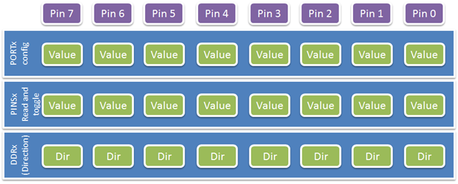
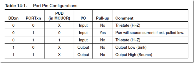
Direction and Data Registers
When you want to use pins on a port, you should configure its
pins as input or output. For Port A, this involves the DDRA (Port A
Data Direction Register). This is another 8 bit register which
defines the direction for each pin: 1 is output, 0 is input.
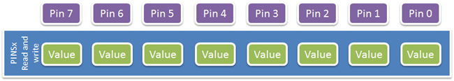
Also, when reading and writing values, you don't always use the
same register.
You have to read the data sheet about 100 times to make sense of
these groups. When compared to the xmega, I found the uses a bit
opaque. So, here's my summary:
- To mark a pin as input, write a 0 to the appropriate bit in the
DDRx register.
- To mark a pin as output, write a 1 to the appropriate bit in
the DDRx register
- To read the value of a pin, check the appropriate bit in the
PINx register
- To TOGGLE the value of a pin, write to the appropriate bit in
the PINx register
- This means you need to read the pin value before you toggle
it.
Beyond that, there are some other registers that affect the
entire port. This table is useful for figuring out what they
do.
Basic Implementation
Let's first look at an implementation that looks like C code in
a CPP file. We'll use that as the benchmark for the rest of the
application.
Creating the project
First, I assume you have Atmel AVR Studio 5.1 installed on your
machine. If not, please refer to the two previous posts linked at
the top of this post. I'm also going to be using a
JTAGICE-compatible programmer and debugger here, also covered in
that previous post.
Create a new project in AVR Studio 5.1. If you're running only
5.0, you won't see the C++ options unless you have the C++ add-in.
Also notice how these show up under "C/C++" and not under the
board-specific folders. We won't be using the board templates
here.
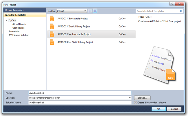
I named the project AvrBlinkenLed.
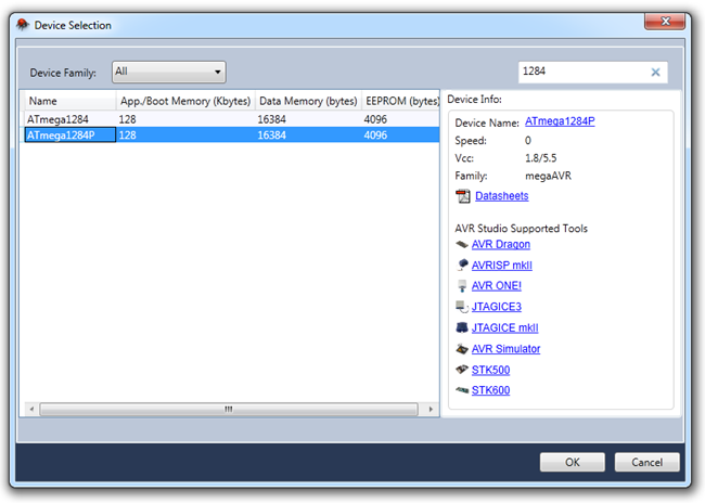
The next step is to pick the processor. Make sure you pick the
one you're using. I'm using the ATmega1284P. The easiest way to
find your processor is to enter its model number in the search box
at the upper right.
Once you select the processor, Visual Studio will load up the
project template and put you right in the main .cpp file. You'll
want to adjust a couple things before you do any real coding,
however.
Setting clock speed and Debugger
Next, we'll need to set the clock speed. You could leave it at
the default 1Mhz, as we're not doing anything special here.
However, why not bump it up to 8Mhz? To do that, we'll need to make
changes in a few places. First, we'll need to actually set the
value on the chip. In this case, we only need to clear the
multiplier fuse which forces the ship at 1MHz by default.
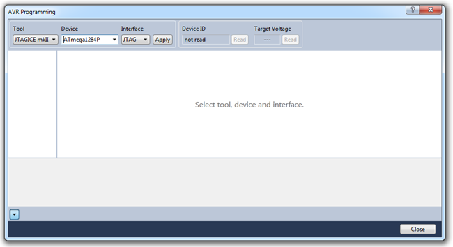
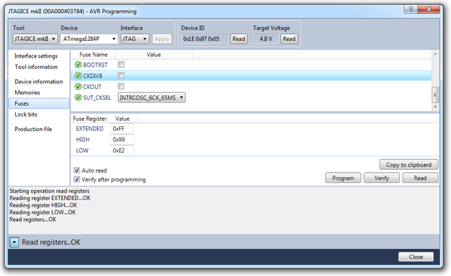
Go into Tools | AVR Programming. After a moment, the AVR
Programming tool will come up. It'll look for your JTAG programmer
and, if found, will display it in the tool list at the left and the
found MCU in the Device drop down to its right. If it was not
found, your JTAG programmer/ debugger is not set up correctly, or
your board isn't connected. Refer to the manufacturer instructions
to fix that before going any further.
If you only have the one JTAG programmer/debugger installed, and
aren't doing any chaining of devices (if you're reading this post,
you almost certainly are not) simply click the "Apply" button to
pull back the MCU information. Click on the "Fuses" tab.
WARNING: Setting some fuses or lock bits can
brick your MCU and require special high-power parallel
programming to reset it. Be sure you completely understand
the purpose of a given fuse or lock before you do anything with
it.
I had already cleared the CKDIV8 fuse in my MCU. If you just got
yours, it will be set. What this does is divide the 8MHz clock down
so you get a CPU clock of 1MHz. Clear that fuse, and only that
fuse, and then click the "Program" button on the right. Make sure
if works.
While there, make sure the JTAGEN fuse is set so you can use the
JTAG debugger. If not set, set it and program that one fuse
setting.
Next, go into the project properties (right-click the
AvrBlinkenLed project and select "Properties") and click the "Tool"
tab. This is where you set up the programmer/debugger to use.
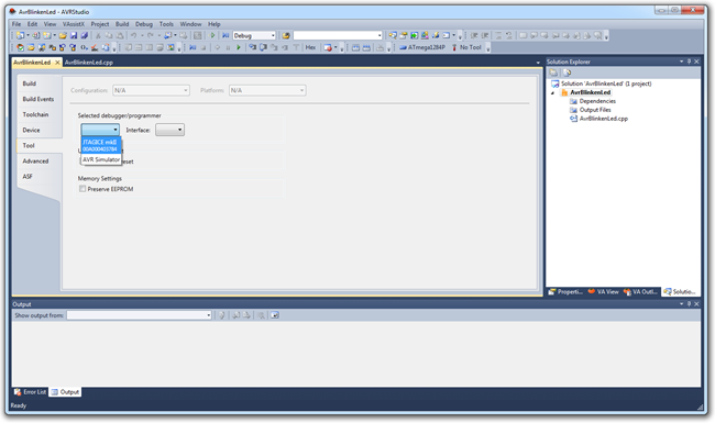
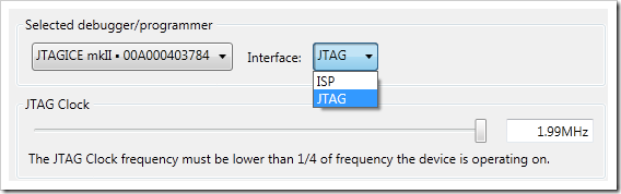
Pick the JTAG programmer from the list. Once you do that, change
the interface on the right to JTAG so you can debug. By default, it
is ISP (In System Programmer) which only allows programming. Then
change the JTAG clock so it's some value lower than 8Mhz / 4.
Finally, we'll define a compiler constant in the main file. The
F_CPU constant is a standard approach you'll see often. In fact, if
you use some of the AVR libraries, they require that specific
constant to be set.
/*

 * AvrBlinkenLed.cpp

 *

 * Created: 1/15/2012 4:21:24 PM

 *  Author: Peter.Brown

 */

#define F_CPU 8000000

//#include <avr/io.h>


int main(void)

{

    while(1)

    {

        //TODO:: Please write your application code

    }

}
That's the default template with the addition of the F_CPU
constant.
Also note that I commented out the io.h include.
We're going to do things from scratch here. The code
doesn't do anything yet, though, although it does compile.
A few more helpful constants and macros
One reason straight C code tends to be so efficient, is that
there are almost no constants, enums, or variables in use for
chip-specific stuff. Instead, most everything is done in the
preprocessor, which ends up resolving down to pointer
manipulation.
We're not taking that approach here, but we'll still use some
constants to help us out.
Add a new include file to the project, named ATmega1284P.h
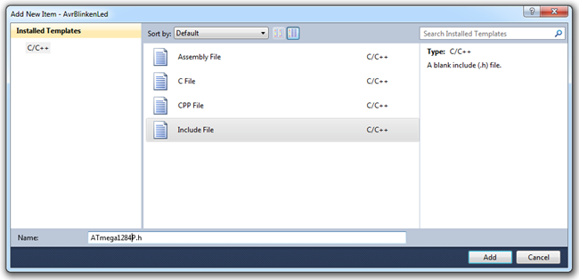
The file will contain the processor-specific constants and types
we want to use. In this case, the addresses for the registers.
/*

 * ATmega1284P.h

 *

 * Created: 1/15/2012 4:41:26 PM

 *  Author: Peter.Brown

 */


#ifndef ATMEGA1284P_H_

#define ATMEGA1284P_H_


typedef volatile unsigned char register8_t;


#define PINA    (*(register8_t*) 0x20)

#define DDRA    (*(register8_t*) 0x21)

#define PORTA   (*(register8_t*) 0x22)


#endif /* ATMEGA1284P_H_ */
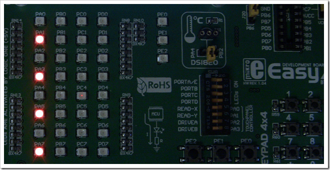
Once you do that, we have enough to be able to turn the LEDs on
or off. We're going to light the LEDs in a pattern as shown in this
photo. You can see from the little diagram on the board (under the
RoHS symbol) that the LEDs are configured in current source
configuration, so setting them to 1 will light them up.
Here's the code for the main file. Doing this will set the above
pattern for the LEDS.
/*

 * AvrBlinkenLed.cpp

 *

 * Created: 1/15/2012 4:21:24 PM

 *  Author: Peter.Brown

 */

#define F_CPU 8000000


#include "ATmega1284P.h"


int main(void)

{

    DDRA = 0b11111111;

    PINA = 0b10101010;


    while(1)

    {

        //TODO:: Please write your application code


    }

}
In this code, I set all 8 pins to output, and then set
alternated pins to 1 to set them to high (it actually
toggles the pin value, but because they were all low (0) to begin
with, this works). In a current source configuration,
where the LEDs get their voltage from the MCU and the MCU is the
source of the current, setting the pin to high will cause the LED
to light. If they were in a current sink configuration, where the
MCU provides ground reference, setting them to low (0) would light
the LEDs. The LED class we create will support either
configuration.
Deploying and Running
To deploy the code, first compile. You'll see output which
states how small the code is (178 bytes total, wow!)
------ Build started: Project: AvrBlinkenLed, Configuration: Debug AVR ------

Build started.

Project "AvrBlinkenLed.cppproj" (default targets):

Target "PreBuildEvent" skipped, due to false condition; ('$(PreBuildEvent)'!='') was evaluated as (''!='').

Target "CoreBuild" in file "C:\Program Files (x86)\Atmel\AVR Studio 5.1\Vs\Compiler.targets" from project "D:\Documents\Docs\Projects\AvrBlinkenLed\AvrBlinkenLed\AvrBlinkenLed.cppproj" (target "Build" depends on it):

    Task "RunCompilerTask"

        C:\Program Files (x86)\Atmel\AVR Studio 5.1\make\make.exe all

AvrBlinkenLed.cpp

        Invoking: AVR8/GNU C++ Compiler

        "C:\Program Files (x86)\Atmel\AVR Studio 5.1\extensions\Atmel\AVRGCC\3.3.1\AVRToolchain\bin\avr-g++.exe" -funsigned-char -funsigned-bitfields -O1 -fpack-struct -fshort-enums -g2 -Wall -c  -mmcu=atmega1284p   -o"AvrBlinkenLed.o" ".././AvrBlinkenLed.cpp"

        Finished building: .././AvrBlinkenLed.cpp

        Building target: AvrBlinkenLed.elf

        Invoking: AVR8/GNU C++ Linker

        "C:\Program Files (x86)\Atmel\AVR Studio 5.1\extensions\Atmel\AVRGCC\3.3.1\AVRToolchain\bin\avr-g++.exe" -o AvrBlinkenLed.elf  AvrBlinkenLed.o   -Wl,-Map="AvrBlinkenLed.map" -Wl,-lm   -mmcu=atmega1284p

        Finished building target: AvrBlinkenLed.elf

        "C:\Program Files (x86)\Atmel\AVR Studio 5.1\extensions\Atmel\AVRGCC\3.3.1\AVRToolchain\bin\avr-objcopy.exe" -O ihex -R .eeprom -R .fuse -R .lock -R .signature  "AvrBlinkenLed.elf" "AvrBlinkenLed.hex"

        "C:\Program Files (x86)\Atmel\AVR Studio 5.1\extensions\Atmel\AVRGCC\3.3.1\AVRToolchain\bin\avr-objcopy.exe" -j .eeprom --set-section-flags=.eeprom=alloc,load --change-section-lma .eeprom=0 --no-change-warnings -O ihex "AvrBlinkenLed.elf" "AvrBlinkenLed.eep" || exit -j .eeprom --set-section-flags=.eeprom=alloc,load --change-section-lma .eeprom=0 --no-change-warnings -O ihex "AvrBlinkenLed.elf" "AvrBlinkenLed.eep" || exit 0

        "C:\Program Files (x86)\Atmel\AVR Studio 5.1\extensions\Atmel\AVRGCC\3.3.1\AVRToolchain\bin\avr-objdump.exe" -h -S "AvrBlinkenLed.elf" > "AvrBlinkenLed.lss"

        "C:\Program Files (x86)\Atmel\AVR Studio 5.1\extensions\Atmel\AVRGCC\3.3.1\AVRToolchain\bin\avr-size.exe" -C --mcu=atmega1284p  "AvrBlinkenLed.elf"

        AVR Memory Usage

        ----------------

        Device: atmega1284p

        Program:     178 bytes (0.1% Full)

        (.text + .data + .bootloader)

        Data:          0 bytes (0.0% Full)

        (.data + .bss + .noinit)

    Done executing task "RunCompilerTask".

Done building target "CoreBuild" in project "AvrBlinkenLed.cppproj".

Target "PostBuildEvent" skipped, due to false condition; ('$(PostBuildEvent)' != '') was evaluated as ('' != '').

Target "Build" in file "C:\Program Files (x86)\Atmel\AVR Studio 5.1\Vs\Avr.common.targets" from project "D:\Documents\Docs\Projects\AvrBlinkenLed\AvrBlinkenLed\AvrBlinkenLed.cppproj" (entry point):

Done building target "Build" in project "AvrBlinkenLed.cppproj".

Done building project "AvrBlinkenLed.cppproj".


Build succeeded.

========== Build: 1 succeeded or up-to-date, 0 failed, 0 skipped ==========
The next step is to take the hex file that was created and load
that to the board via the JTAG programmer. Go under Tools | AVR
Programming again, and select the "Memories" tab after hitting
"apply" to pull up the ATmega we're using.
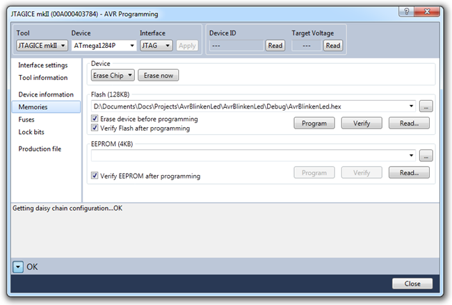
Select the hex file from your project. You can see where it's
located on my file system. The programmer will remember this from
project to project, so always double-check to make sure you're
programming the right code. Once sure, click the "Program" button.
You'll see the following status:
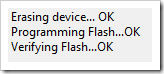
You should immediately see the output on your test board. If
not, close the AVR Programming tool and hit the Reset button on
your board.
Now, all of that is wonderfully efficient, but not particularly
friendly or reusable. So, let's look at how to do this another
way.
First Implementation in real C++
The C code is simple and very tight. However, once you get into
a complex application, the code can get confusing and jumbled. The
nature of a language like C requires extreme discipline to keep the
code compartmentalized and reduce dependencies between the
different modules. Often times, the developer will trade away some
of that for the sake of performance or code size. The AVR libraries
that come with AVR Studio include a fair bit of that.
To be clear, you can write very good code in C as long
as you have discipline. You can also write crap code in
C++, but the compiler and language give you a few more things to
help you do the right thing.
The IOPort class
In my first version of this code, I created an IOPin class
rather than IOPort. I did this because I wanted to make my library
smell a bit like the NETMF libraries where you code against
DigitalInput and DigitalOutput classes. However, that meant
creating an instance of the class for each pin you wanted to
manipulate - an entire class for 3 bits (literally, bits) worth of
data. It also didn't allow me to group operations at the port
level. So, in the version I'm presenting here, I went at it at the
port level with the IOPort class.
First, create a header file named IOPort.h
/*

 * IOPort.h

 *

 * Created: 1/15/2012 5:43:58 PM

 *  Author: Peter.Brown

 */


#ifndef IOPORT_H_

#define IOPORT_H_


#include "ATmega1284P.h"


enum PinDirection

{

    DirectionInput = 0,

    DirectionOutput = 1

};


class IOPort

{

protected:

    volatile register8_t* _port;

    volatile register8_t* _pins;

    volatile register8_t* _ddr;

public:

    IOPort(register8_t* portRegister, register8_t* pinsRegister, register8_t* ddrRegister) :

        _port(portRegister),

        _pins(pinsRegister),

        _ddr(ddrRegister) {}


    void SetPortDirection(register8_t directionBits);

    void SetPortValues(register8_t valueBits);

    void GetPortValues(register8_t &valueBits);


    void SetPinDirection(int pin, PinDirection direction);

    void SetPinValue(int pin, bool value);

    void GetPinValue(int pin, bool &value);

};


#endif /* IOPORT_H_ */
You can see the class has separate methods for working with
individual pins versus the entire port. In that way, we can do bulk
port operations and individual pin operations from the same class.
We can get away with that here, unlike in the .NET Micro Framework,
because we know that all the AVR pinsNow for the implementation.
Create a code file IOPort.cpp
/*

 * IOPort.cpp

 *

 * Created: 1/15/2012 6:03:06 PM

 *  Author: Peter.Brown

 */


#include "IOPort.h"


void IOPort::SetPortDirection(register8_t directionBits)

{

    *_ddr = directionBits;

}

void IOPort::SetPortValues(register8_t valueBits)

{

    *_pins = valueBits;

}

void IOPort::GetPortValues(register8_t &valueBits)

{

    valueBits = *_pins;

}


void IOPort::SetPinDirection(int pin, PinDirection direction)

{

    // assumes pin is correctly in the range of 0..7

    if (direction == DirectionOutput)

        *_ddr |= (1 << pin);

    else

        *_ddr ^= (1 << pin);

}


void IOPort::SetPinValue(int pin, bool value)

{

    // assumes pin is correctly in the range of 0..7


    // if the pin was already high and we want it high, do nothing.

    // if the pin was already low and we want it low, do nothing.

    // if the pin was high, and we're requesting low, toggle it

    // if the pin was low, and we're requesting high, toggle it


    if (*_pins & (1 << pin))

    {

        // pin is currently high


        if (!value)

            *_pins = (1 << pin);    // toggle pin because we want it low

    }

    else

    {

        // pin is currently low


        if (value)

            *_pins = (1 << pin);    // toggle pin because we want it high

    }


}


void IOPort::GetPinValue(int pin, bool &value)

{

    value = (bool)(* _pins & (1 << pin));

}
Note how writing a 1 to the pin doesn't set it high, it toggles
it. That means we need to read the current value of the pin, and
then decide whether it needs to be toggled or not.
This IOPort class doesn't support everything. For example, I
haven't included here the code to set the pull-up resistors. I also
didn't add anything optional to the constructor to set initial
direction or values from that call. However, it works for our
purposes in this example.
Supporting multiple types of processors
In the code I'm using for my own projects, I don't include the
processor-specific include file in every class. Instead, I include
a common include file which has a preprocessor constant for the
processor I'm using and then makes a decision as to which
processor-specific include file to pull in. I blatantly stole this
idea from the AVR libraries, as it's a good one.
Lighting up some LEDs
Now to light up some LEDs. I very slightly changed the pattern
so you can be sure you're seeing the newly flash firmware, and not
the original version. Here's the new code for the main
function.
/*

 * AvrBlinkenLed.cpp

 *

 * Created: 1/15/2012 4:21:24 PM

 *  Author: Peter.Brown

 */

#define F_CPU 8000000


#include "ATmega1284P.h"

#include "IOPort.h"


int main(void)

{

    //DDRA = 0b11111111;

    //PINA = 0b10101010;


    IOPort portA(&PORTA, &PINA, &DDRA);


    portA.SetPortDirection(0xFF);

    portA.SetPortValues(0b10101111);


    while(1)

    {

        //TODO:: Please write your application code


    }

}
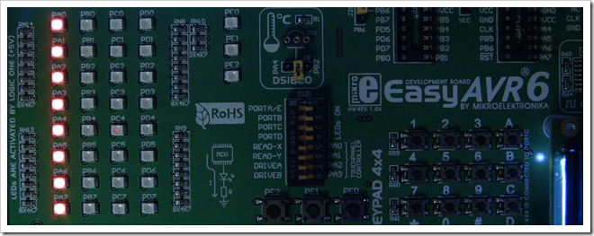
Program it on the MCU and look at the LEDs. You should now see
pins 0-3 lit up, as well as pins 5 and 7. This works because the
pins were, by default, all low. Calling SetPortValues
toggles all the values for that port. If you called it
again with the same pattern, they'd all turn off.
I prefer the ATxmega approach
The ATxmega (the follow-on to the ATmega) has a couple different
registers to accomplish the task of setting the pin value. One is
OUTSET where any set bits cause the pins to go high. The other is
OUTCLR where any set bits cause the pins to go low. In that way,
you don't have to do a read-compare-modify cycle. If that chip were
available in PDIP so creating DIY kits for other people who don't
want to surface mount solder, I'd be in heaven.
As to size: if I comment out the Pin-specific functionality, in
order to get a fair comparison with our original program, the
program compiles to 320 bytes. Compare that to the 178 bytes of the
macro-version. It's a bit under twice the size for this tiny
program. Whether that's a concern to you is, well, your concern :)
If you leave in the pin-specific functionality, you get around 510
bytes. On a processor with 128K, that's not a big deal, but if
you're looking at a processor with only 2K total memory, that can
certainly be an important distinction. At the different levels of
optimization, I get the following program sizes:
| Optimization level |
Program Size in Bytes |
| None (-O0) |
856 |
| Optimize (-O1) default |
512 |
| Optimize more (-O2) |
496 |
| Optimize most (-O3) |
496 |
| Optimize for size (-Os) |
484 |
The different optimization levels certainly make an impact on
size. Beware, though, as sometimes optimization can make the code
larger, or slower. It can also make it more difficult to debug or
trace. I tend to leave the optimization on the default -O1.
In addition, you can definitely trim this down a bit by removing
some of the conversions, the enum, and doing a little more
optimization. You can even do a little inline assembly, but I'm not
a big fan of the AVR G++ approach to that, using strings. I used to
write a fair bit of inline assembly in Borland C++ for DOS, and to
do that, you simply had an asm block with statements in it like asm
{ mov AX, AY }.
Without actually trying it, I suspect that the code to construct
the string would take up more space than the inline assembly would
give us back, so I'm going to leave it out of this example.
Abstracting Away LED Behavior
LEDs can be connected a two main ways: in current source or
current sink configuration. I would like to create an LED class
which properly works regardless of how you hook up the
LEDs.
Create a header file named Led.h
/*

 * Led.h

 *

 * Created: 1/15/2012 7:12:19 PM

 *  Author: Peter.Brown

 */


#ifndef LED_H_

#define LED_H_


#include "ATmega1284P.h"

#include "IOPort.h"


enum LedConfiguration

{

    LedCurrentSource,

    LedCurrentSink

};


class Led

{

protected:

    IOPort*                _port;

    LedConfiguration    _configuration;

    uint8_t                _pin;


public:

    Led(IOPort* port, uint8_t pin, LedConfiguration configuration) :

        _port((IOPort *)port),

        _configuration(configuration),

        _pin(pin) {};


    void TurnOn();

    void TurnOff();

};


#endif /* LED_H_ */
Next, create the implementation file Led.cpp. The code in this
file will set the pin values based on whether or not we're in
Source (1 to light) or Sink (0 to light) mode.
/*

 * Led.cpp

 *

 * Created: 1/15/2012 7:18:36 PM

 *  Author: Peter.Brown

 */


#include "Led.h"


void Led::TurnOn()

{

    _port->SetPinValue(_pin, (_configuration == LedCurrentSource));

}


void Led::TurnOff()

{

    _port->SetPinValue(_pin, !(_configuration == LedCurrentSource));

}
To make that work, we're going to need another type, so let's
add the following to the processor-specific header file
ATmega1284P.h. At the same time, we'll change the
definition of register8_t to use this type.
typedef unsigned char uint8_t;

typedef volatile uint8_t register8_t;
I need uint8_t because I'm keeping the pin number in the class,
and don't want to allocate a whole 16 bit int to hold a number
between 0 and 7. Memory on these devices is even more scarce than
program memory so you want to use small types to keep the stack
small and the data (if you allocate any) small.
Why no New Operator?
You'll notice that I'm not using the new operator anywhere,
instead I'm allocating everything as local variables. At some
point, I may change that, but at least for now, the price isn't
worth it. Adding in the new operator, and all the malloc stuff it
requires, adds a huge amount of code to your application. By
default, AVR G++ doesn't include it in so you can save that
4-10k.
The new main function looks like this:
/*

 * AvrBlinkenLed.cpp

 *

 * Created: 1/15/2012 4:21:24 PM

 *  Author: Peter.Brown

 */

#define F_CPU 8000000


#include "ATmega1284P.h"

#include "IOPort.h"

#include "Led.h"


int main(void)

{

    IOPort portA(&PORTA, &PINA, &DDRA);


    portA.SetPortDirection(0xFF);

    //portA.SetPortValues(0b10101111);


    Led ledA0(&portA, (uint8_t)0, LedCurrentSource);

    Led ledA1(&portA, (uint8_t)1, LedCurrentSource);

    Led ledA2(&portA, (uint8_t)2, LedCurrentSource);

    Led ledA3(&portA, (uint8_t)3, LedCurrentSource);

    Led ledA4(&portA, (uint8_t)4, LedCurrentSource);

    Led ledA5(&portA, (uint8_t)5, LedCurrentSource);

    Led ledA6(&portA, (uint8_t)6, LedCurrentSource);

    Led ledA7(&portA, (uint8_t)7, LedCurrentSource);


    ledA0.TurnOn();

    ledA1.TurnOn();

    ledA2.TurnOn();

    ledA3.TurnOn();

    ledA4.TurnOn();

    ledA5.TurnOn();

    ledA6.TurnOn();

    ledA7.TurnOn();


    while(1)

    {

        //TODO:: Please write your application code


    }

}
Rather than inherit LED from the port, as I did in the pin-based
version in some other code I've written, I decided to have the LED
simply take in an instance of the port. The LED class assumes
you've already configured the LED pin as output, as that is an
operation that is often done an entire port at a time. Again,
another small concession to efficiency without sacrificing the main
benefits of C++.
If you want to test that the led is properly toggling the
values, uncomment the SetPortValues call there to give the port
some initial values. Or, you can just make the LEDs toggle like we
will in the next post.
At this point, if you run the application, you should see all
eight LEDs lit
In the next post, we'll learn what it's going to take to blink
these LEDs with a specified time interval.