In the wee hours of the night, I've been continuing to learn how
to develop for the various AVR family chips from Atmel. I also do a
lot with NETMF, Netduino, and the .NET Gadgeteer, but sometimes
(despite the pain!) it feels good to code right on the metal.
Introductory/getting started information for the AVR family is
not always the easiest to find, so this post covers a few other
important details I think you'll find helpful.
Select the MCU
MCUs vary wildly in capabilities. Which MCU you choose for
tinkering isn't hugely important, but if you have any sort of
project in mind, you'll want to try and narrow it down to a family.
The programming model is not identical across different families,
and capabilities can vary in significant ways. Here are a few
things to consider:
- Do I need to limit myself to those offered in a PDIP package in order
to make it easy for DIY use? Most people in the DIY community are
not able to solder the zillion pins on the smaller surface mount
packages. The more powerful the chip (and I define "powerful" very
loosely here) the harder it will be to find a PDIP package. In
those cases, you may need to rely on a
vendor's own carrier boards.
- How many USARTS (sync/async serial communication) do I need?
Serial is important for microcontroller to device
communication
- How many I/O pins to I need?
- How speed-intensive is my code?
- How much program memory do I expect to require
For this project, I chose the ATmega1284P. I chose this
because
- It is offered in a 40 PDIP, so it is DIY friendly
- It is inexpensive at
under $6 per unit in very small quantities.
- It has the most memory of any AVR PDIP package MCU
- It has two USARTs for serial communication
- It supports SPI so I'll be able to use the SPI DACs I'm playing
with
- It supports JTAG programming and debugging
Note that speed wasn't really a concern. You'll be amazed at how
much you can accomplish in native code on an MCU running at just a
couple MHz. Amazing!
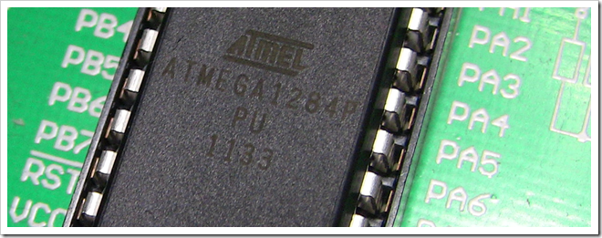
Whatever microcontroller you choose, make sure you know what
clock speed it's running at. It's not as simple as buying a 20Mhz
MCU and saying it's running at 20Mhz. By default, some of the MCUs
run at 1MHz to make sure you can program them with anything. Beyond
that, you can change the speed using "fuses" (flags set on the chip
outside of your program memory), external clock sources, and code
in your application.
For example, the development board I use (more on that in a
moment) has an 8MHz crystal oscillator on the board. I had
incorrectly assumed that the chip was running at 8MHz. However, I
stumbled across the following in the datasheet for the chip:

Aha! So many things rely on you knowing the correct clock speed,
that if you get it wrong, you'll find half your code simply
fails.
Get the Data Sheets
In the case of Atmel, finding the data sheets is pretty easy.
What's confusing is that there will often be more than one version
floating around, and they're not always updated correctly. In
addition, newer chips like the XMega I played with previously, have
a fair number of errors in the data sheet.
The way to find the sheet is to go to the Atmel site and browse
for your chip. First pick the architecture
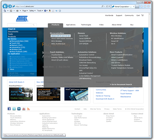
Then, and the bottom left, pick the family
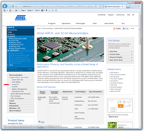
In this case, I chose "megaAVR" as that's the family the MPU I
chose belongs to. It's next to my awesome MSPaint arrow there on
the left.
Next, scroll down and pick the model that's written on your
chip.
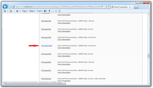
You can, of course, simply type your chip's name into
Bing/Google and see what comes up. Just ignore all those
third-party datasheet sites. They're the usual link bait crap you
find on the internet.
You'll eventually make your way to the MCU's product page on the
Atmel site.
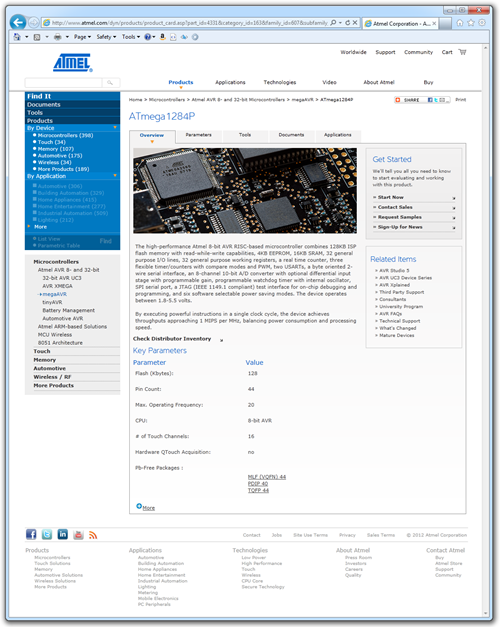
These product pages are really nice, especially when you're
doing the initial research to figure out which MCU to choose.
Finally, clock on the "documents" tab at the top. The first two
documents for any given MCU will typically be a short summary,
useful when investigating capabilities, and then a a full data
sheet.
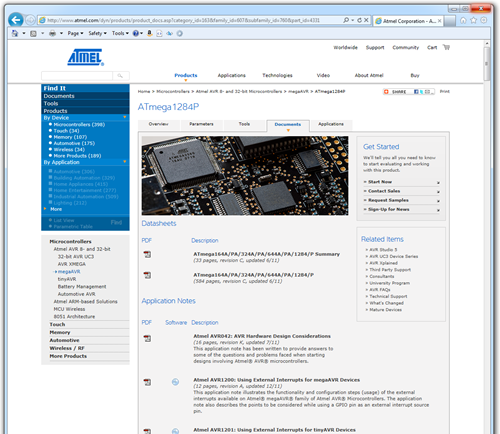
Now, here comes the fun part with Atmel. Make note of the
various MCUs listed in the data sheet. That means they all follow
the same design, but differ in something relatively trivial like
the amount of program or flash memory on board. Now, look up the
data sheets for a couple of those and see if they're any later than
this one. Atmel doesn't always do a good job of making sure the
data sheets make it out to all the right places on their site.
It'll only take a moment.
With the MCU chosen, the next step is to buy or build something
to host it.
Optionally, Pick up a Development Board
When getting started, using a development board is almost always
the easiest approach. Atmel makes a number of nice development
boards for their MCUs. One great thing about them is that the
development environment has templates and examples build around
those.
You can also find relatively inexpensive development boards on
ebay. My experience with those has been pretty spotty: if it works,
awesome. If it doesn't work, support is pretty non-existent and the
language barrier makes self-help on the sites almost
impossible.
Despite the lack of direct support for them in AVR Studio, I'm
really partial to the Mikroelektronika boards. They are extremely
well made, and feature-rich without getting in your way. This
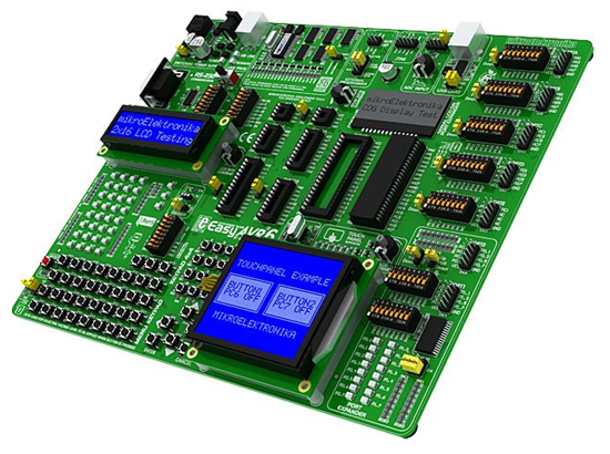
EasyAVR6 is one that I put on my Christmas list and found under
the tree on December 25 :) The board is not tiny, it's about the
size of a mini ATX motherboard. Also note that it does not come
with the two LCD screens, those must be purchased separately from
Mikroelektronika. They're inexpensive enough, though.
Considerations when picking a board:
- Does it support the MCU(s) I plan to use?
- Is there native support for it in my dev environment? It's not
necessary, but it removes some barriers to getting started
- Does it break out all the pins in a way that is easy to use? In
the AVR6, the pins are all broken out in the headers on the
right
- Does it break out key features in ways I plan to use them
(RS-232 connector, display, buttons, LEDs)
- Does it include debug LEDs so I can easily see the status of
any pin? (not necessary, but VERY helpful)
- Is it built well, well-supported, and easy to use?
You can go with less expensive boards, of course.
MikroElektronika makes a much smaller Ready for AVR board which supports the 40 pin
AVR chips like this one. It doesn't have any debug LEDs or buttons,
but it has all the required oscillator circuitry and pin headers.
It also supports USB deployment, but does not include a JTAG header
for debugging. This is not a show-stopper, but I personally
consider it critical for non-trivial work.
Here's an example of the debug LEDs in use on my board
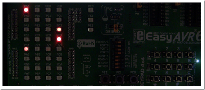
Each LED on the left corresponds to one pin. They're labeled so
I can easily see that Port A, Pin 0 and Pin 4, and Port D pins 2
and 3 are all high. This is incredibly helpful when writing your
applications.
Whatever development board you choose, you'll ideally want to
make sure it breaks out the interface for debugging the MCU, so you
can attach a debugger to it.
Get a Debugger and Programmer
Most development boards include nice on-board USB
programming. One thing none of them provide is any
sort of USB debugging. For those of us used to
single-stepping through code and adding breakpoints, inspecting
values, etc., this can be a real step backwards in usability.
Without a debugger, all you can do is debug using tricks like
blinky lights and (eventually) outputting messages to an LCD (but
that comes MUCH later). It's time-consuming and can be
frustrating.
For AVR programming in AVR Studio 5.1, one of the best consumer
debuggers is the JTAGICE Mk3 from Atmel. The problem is, this thing
costs $300!
There is one good chinese clone of this device. It's a reverse
engineering of the protocol, not a blatant copy like some others. I
recommend this one above all else. It's called the JTAGICE mkII-CN
by Mcuzone. Make sure you get the red-case one branded by
Mcuzone, and none of the other copies. It runs around $80.
Get it shipped DHL, don't use China Post.
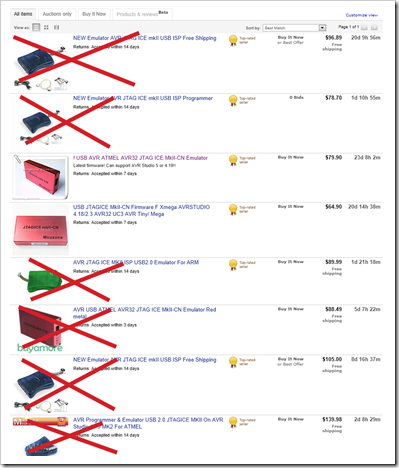
I did a quick ebay search on JTAGICE and crossed off the ones I
do not recommend getting. Notice how one of those is the red box.
It doesn't say "mcuZone" on it, so it may very well be a clone.
You want one which says mcuZone and has the serial number
tag on the bottom. That version comes build for use with
AVR Studio 4, but includes a firmware update to work with AVR
Studio 5.
Some of the other units are blatant copies of other people's IP,
so I'd rather not support those.
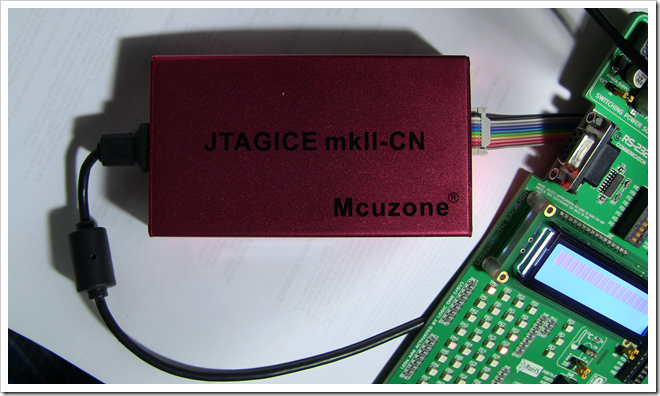
Again, get it shipped DHL even though that costs a bit more.
It's much faster and far more reliable.
You'll also need to make sure the test board you use has a debug
port of some sort. For the larger AVR chips, that will almost
always be JTAG, although there are other options.
Set up the IDE
AVR Studio 5.1 is build on Microsoft Visual Studio 2010 Isolated
Shell. That means current Visual Studio developers will feel pretty
comfortable with the IDE.
I previously covered using AVR Studio 5 in this blog post.
In that one, I used the Ready for XMEGA board. That's a great
board, but the XMEGA is a surface mount device. If surface mount
isn't a concern, I highly recommend it as that chip has a lot of
great capabilities and that board is nice and inexpensive…and
includes a JTAG deployment/debugging report.
Atmel has released a beta of version 5.1. I found the link to
that on the avrfreaks AVR Studio 5 forum. Be sure to visit
there to get it, as the links change, and there may be a later
version out by the time you read this.
Version 5.1 supports C++ right in the box, which was key to what
I want to do. Note, however, that if you go C++, you're pretty much
on your own. All the templates are for C and/or assembly. I was ok
with that, though, as I actually found it easier to learn
everything by discarding the AVR software framework that the
templates use.
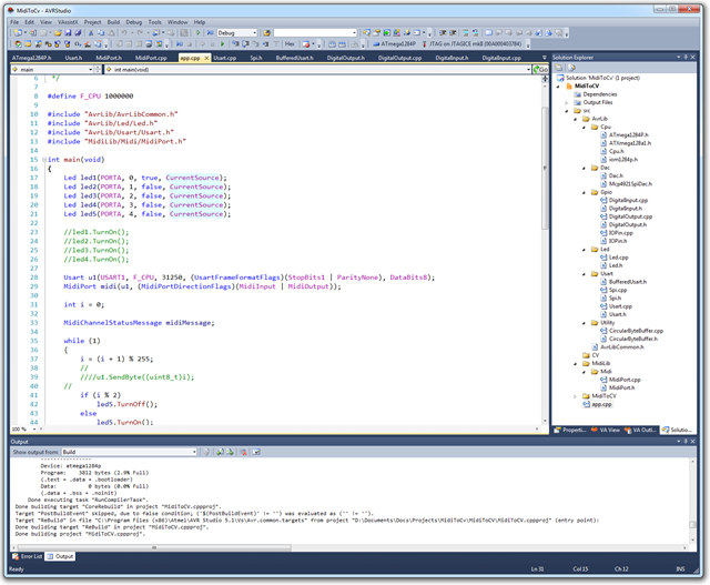
Looks familiar, doesn't it? That's a MIDI to CV project I've
been working on. The AVR library I'm building is from scratch,
primarily because I want to learn the chip without someone else's
framework obscuring the details. Oh, and because I want to write
C++ :) Still, the optimized byte size of this app so far is about
2k. In this screen shot, I had turned optimization off as I was
trying to figure out why JTAG wasn't working. Speaking of that…
Important IDE Settings for JTAG Debugging
The external hardware debuggers are pretty much the only choice
when it comes to actually debugging the chip. It's things like this
that make you realize just how much the .NET Micro Framework is
doing for you behind the scenes.
JTAG debugging has some important considerations with regard to
the speed it runs at. This one tripped me up for quite a while.
Remember earlier I said you need to know what clock speed you're
running the MCU at? Here's one place where it makes a huge
difference.
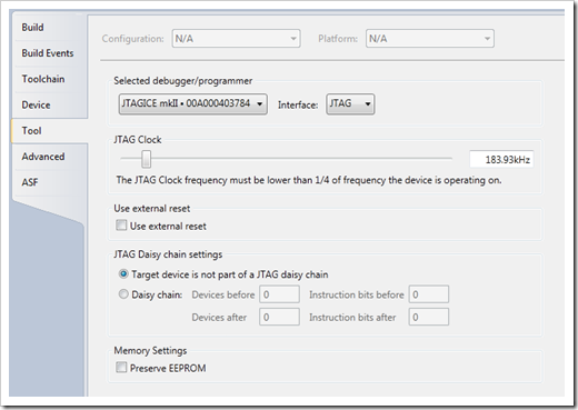
Notice the JTAG clock slider, and the note under it. If JTAG
debugging isn't working, here's one place to check. By default, the
slider was set at 1MHz. By default, the MCU was also running at
1MHz. So, once I slid the slider down to around 200Mhz (which was
automatically corrected to the multiplied value you see above),
JTAG debugging started working! Yay!
One you have that, you can set breakpoints and single-step
through your code just like you thought you should. If you bump up
the CPU speed on the processor, be sure to come back here and bump
this up as well, so you get the most speed out it.
