As much as I like the .NET Micro Framework, and especially the
.NET Gadgeteer line, I've been itching to try a little C/C++
for specific functions on boards. Consider things like chip
controllers and stuff to offload work from the main micro
controller, much like all those chips on your PC motherboard are
doing to help the CPU. Generally, this is not a
job for the .NET Micro Framework, although it can still be the main
brain of the system.
There are lots of different types of microcontrollers out there,
with the big three being ARM (which many vendors/manuifacturers
license), AVR (Atmel only) and PIC (Microchip technology chips
that have been around forever).
For playing around at the moment, I chose an AVR MCU on a
test board. I haven't committed to any particular MCU for any
projects yet. My main criteria is simply that I be able to code in
C/C++ and not be forced to use assembly unless I want real
optimization of a specific feature.
I've ordered a few boards lately, but the first one to arrive
was the MikroElektronika "Ready for Xmega" board. This
is a great little $35 board which includes the ATxmega128A1 (MPU datasheet). The ATxmega128A1 MCU has,
according to Atmel:
- Up to 32MIPS speed (at 32 MHz)
- Low power 8/16 bit architecture
- 128KB flash memory for storing the program
- 2KB EEPROM for the boot section
- 8KB SRAM memory
- 32 registers
- External bus interface for up to 16MByte SRAM and 128Mbit
SDRAM
- 78 IO pins
- 32kHz Real-time Clock
- Eight 16 bit timers
- 16 bit Real time counter
- 1.6 to 3.6v at 0-12MHz
- 2.7 - 3.6v at 0-32MHz
- Four two-wire interfaces
- Four SPI peripherals
- Eight USARTs
- AES and DES Crypro Enginer
- Two 12 bit analog to digital converters with 8 inputs each
- Two 12 bit digital to analog converters (1 continuous or two
sample and hold outputs each)
- bunch of other stuff :)
FWIW, the MPU is also pretty buggy according to all the posts
I've read and the big list of workarounds in the data sheet. I
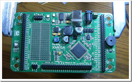
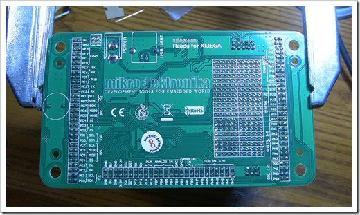
think it'll do, though. Here are a few photos of the board on my
workbench
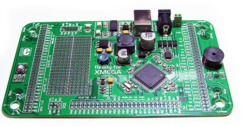
The board adds USB bootloader-based programming, as well as
optional JTAG or PDI programming. For those of us used to Netduino,
Arduino and the like, the bootloader-driven USB approach will feel
the most familiar. For folks who want to just do this on a
breadboard, there are other types of programmers you can use (for
DIP packages, anyway, the surface mount ones need a board of some
type, if only a breakout board)
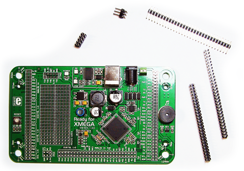
Before I could do anything with the board, I needed to solder on
the headers. The board breaks out each pin to a pair of headers,
and also includes dedicated headers for JTAG and PDI programming.
Here are some photos:
The headers aren't the tallest things on the board, so when
soldering, you need to tack them on; you can't just flip the board
on the table and use gravity to help you.
The way I do it is to tightly hold the header to the board with
thumb and forefinger on my left hand (not touching any pins I'm
about to solder!), then pick up a blob of solder with the soldering
iron, and wipe it across the solder pad and pin on the back just
enough to hold the pin in place. You're not looking for a good
connection like you'd get in a two-handed operation, you want just
enough to hold it in-place for a few minutes. On headers like
these, I do two pins total on each header, in opposite corners. I
then solder the rest of the pins on the header, then come back and
re-solder the two tacked pins to get a good connection.
Now for some programming.
AVR Studio
AVR Studio is Atmel's free development environment for coding
for their 8 and 32 bit AVR micro processors. AVR Studio 5 uses the
Visual Studio 2010 Isolated Shell for the IDE.
This is a product that doesn't get a ton of attention in the
developer community, but makes it easier for other companies to
quickly create developer solutions for their own products.
In this case, it is Atmel AVR Studio 5, which uses the GCC
toolchain for the compiler, and some additional tools for actually
sending bits down to the microcontroller.
Installation
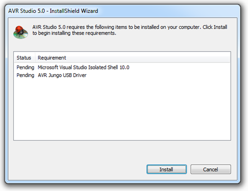
The installer walks you through several different install steps,
including the Visual Studio Shell, the USB driver, and the AVR
tools themselves.
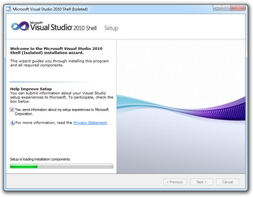
Hey, this looks pretty familiar! The Visual Studio Shell setup
is similar to the regular Visual Studio setup.
Once the shell and USB drivers are installed, you'll get the
setup for AVR Studio itself.
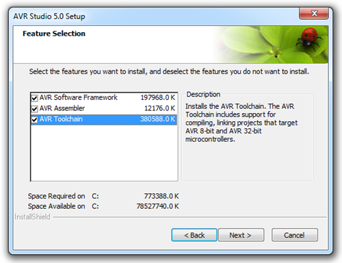
The AVR toolchain consists primarily of GCC tools.
Running AVR Studio
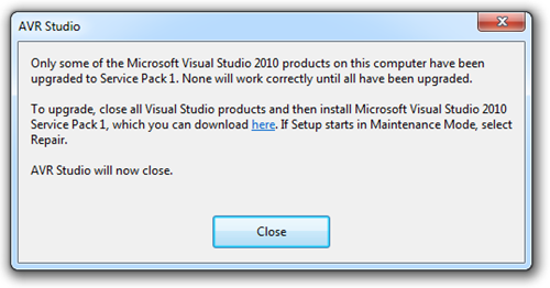
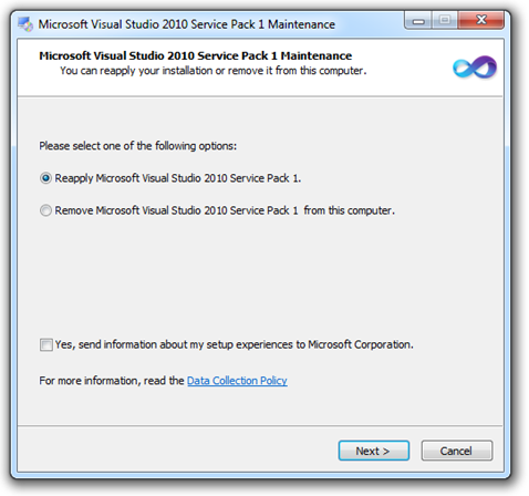
Now, because I have VS2010 SP1 on my machine for normal
development, and AVR Studio 5 doesn't install SP1 by default, I
need to re-apply SP1. How did I know? This is the message I got
when I ran AVR Studio:
The AVR Freaks forums had some folks asking about SP1 and
whether it was ok to install. General consensus was it's fine and
adds some improvements to the shell, but wasn't necessary if that's
all they used Visual Studio for. For those of us who live in Visual
Studio all day, especially SIlverlight developers, SP1 is
definitely required. So, off I go to repair its installation.
Unfortunately, it had to roll back due to the interim build
Silverlight stuff I have, so I had to go uninstall the Silverlight
5 bits then re-install them after the SP was installed. No worries.
It's not like I'm trying to wrap up the last two chapters of a
Silverlight book right this very moment or anything ;)
Rolling back is not a fast process, even on an SSD, so you may
want to take some precautions ahead of time. For example,
uninstalling Silverlight first.
Oddly enough, after the rollback, AVR Studio and everything else
worked, and shows as running SP1. Not sure how I feel about that
but "Comfortable" isn't it.
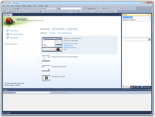
Running AVR Studio Take 2
This looks familiar, but now with a cool ladybug icon. AVR
Studio is working just fine.
For grins, I opened up regular visual studio and verified that I
could still build Silverlight 5 projects as earlier. Yep. No
problems.
Hello World: Yes! Another BlinkenLed Project!
This is quite a bit lower level than what I normally do with
devices like the Gadgeteer. That, plus my lack of experience with
this hardware has made me set my sites for "Hello World" really low
:) In fact, it will be a success if I can simply figure out how to
compile and deploy code to the board.
AVR Studio comes with a ton of sample projects. They also have
project types which target their own demo boards. Because I'm using
a third-party board, I had to pick "user board" as the type of
project. I was then presented with a list of MCUs to pick from, via
a drill-down.
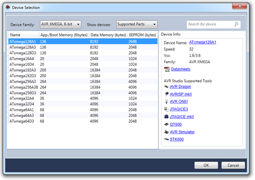
Once I got to the XMEGA family, I picked the one that is on this
board, the 128A1. AVR Studio presented helpful links for that
processor over on the right. Once you've selected your processor,
the targets for the project will be correctly set via the toolchain
entries in the project properties.
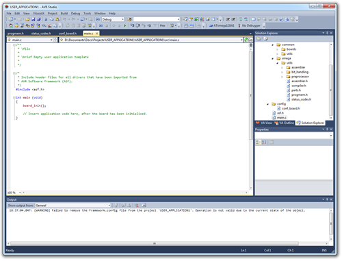
You'll then be tossed into the code editor with the basic
outline of a program already there.
What you do at this point is, of course, up to you. I had no
idea, so I started hunting around on the avrfreaks.net forums until
I found some tutorials. Between that and (mostly by) looking at the
include files (on my machine: C:\Program Files (x86)\Atmel\AVR
Studio 5.0\AVR Toolchain\avr\include\avr ), I was able to put
together some of the important things:
- iox128a1.h contains the IO definitions for the MCU on this
board. There are different definitions for each MCU, but they try
and keep them somewhat source compatible
- The code I found for the ATTINY and other Atmel processors,
using macros like DDRC, doesn't work on this chip. There are
different macros (maybe this is an AVR Studio 5 thing?)
- Pins are grouped into ports.
- When performing output operations, you must first set the I/O
flags for the pins on the port. You do this one entire port at a
time
- You need to specify the CPU speed you want to run at using the
F_CPU define before all other includes. This speed can be lower
than the rated speed of the MPU.
I still had the DerBlinkenLed project on my breadboard from the
Gadgeteer project, so I pulled out the Gadgeteer header and plugged
in the right pins for the Atmel board.
Here's the first version of the program I wrote. DON'T USE THIS,
AS IT DIDN'T WORK.
/**

 * main.c

 *

 * ATxmega128A1 targeted "Hello World" example - Pete Brown

 * THIS IS A NON-WORKING EXAMPLE. SEE LATER EXAMPLE

 */


#ifndef F_CPU

#define F_CPU 32000000UL    // 32MHz clock speed

#endif


#include <avr/io.h>

#include <util/delay.h>


int main (void)

{

    // not doing anything really with the board, so I commented this out

    // and removed the <include <asf.h> from the top as I'm not using the framework

    // board_init();


    // set the directions for Port C.

    // could also use the PORTC_DIR macro

    PORTC.DIR = 0b00000001;


    while (1)    // loop forever

    {

        // PC0 pin is LSB of PORTC value. Could also use the PORTC_OUTSET macro. not sure of any perf difference

        PORTC.OUTSET = 0b00000001;

        _delay_ms(500);


        // turn the port off (LED off)

        PORTC.OUTSET = 0b00000000;

        _delay_ms(500);

    }

}
The problem with this listing is that the LED stayed on 100% of
the time (or at least it appeared that way). I didn't find
that out until after deployment, however.
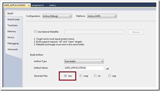
Deploying the application
You need the tools to create the hex file for you. By default,
you get a .elf, but no hex. Go into the project properties, build
tab, and select the option to generate .hex files. Rebuild at that
point.
At this point, I had to insert the DVD that came with the board.
They didn't have the same software available for download online as
far as I can tell so I actually had to put a physical disc in my
drive. That's roughing it!
What do you know? The DVD has example source code for working
with this board. It's not for AVR Studio, but I can probably learn
a few things from it.
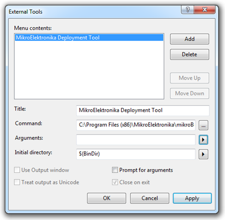
In the end, the bootloader app wasn't actually on the DVD, it's on the web site. There's no installer for
it, so you just need to save it someplace save and set up a
shortcut to it. I recommend adding it to the external tools in
Visual Studio er….AVR Studio, like this:
Run the program and select the correct COM port. I didn't have
the board plugged in when I first started this, so it default to
COM 1. However, I then plugged it in and clicked "Change Settings"
and found COM9 to be the only option. I also recall seeing the
board ID as COM9 when it installed the USB drivers.
Then, reset the board (little button on the left side of the
board) and quickly (within 5 seconds or less), click the "Connect"
button. It will change to "Disconnect" and you'll see the Connected
message in the history window.
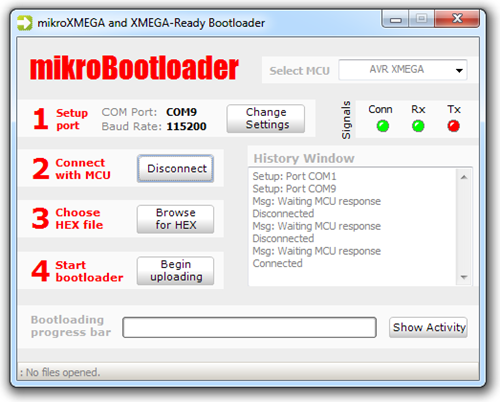
In my screen shot, you can see it took me a few tries to get
within the time limit. I didn't realize there was a time limit
until I read it.
I think browsed for the .hex file and clicked the "Begin
uploading" button.
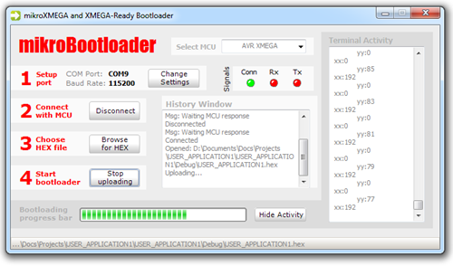
When it completed, I was instructed to reset the MCU (again,
using the button)
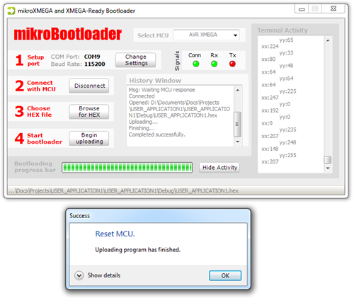
At this point, the program ran, but the LED stayed lit all the
time. Time to figure out why.
I knew it had to do with my code, because the LED was not lit in
the factory default (empty) program.
So, I went back to the iox128a1.h file and looked at the
definition of the PORT structure. I saw that it has a DIR as well
as a DIRSET as shown here:
/* I/O Ports */
typedef struct PORT_struct
{
    register8_t DIR;  /* I/O Port Data Direction */
    register8_t DIRSET;  /* I/O Port Data Direction Set */
    register8_t DIRCLR;  /* I/O Port Data Direction Clear */
    register8_t DIRTGL;  /* I/O Port Data Direction Toggle */
    register8_t OUT;  /* I/O Port Output */
    register8_t OUTSET;  /* I/O Port Output Set */
    register8_t OUTCLR;  /* I/O Port Output Clear */
    register8_t OUTTGL;  /* I/O Port Output Toggle */
    register8_t IN;  /* I/O port Input */
    register8_t INTCTRL;  /* Interrupt Control Register */
    register8_t INT0MASK;  /* Port Interrupt 0 Mask */
    register8_t INT1MASK;  /* Port Interrupt 1 Mask */
    register8_t INTFLAGS;  /* Interrupt Flag Register */
    register8_t reserved_0x0D;
    register8_t reserved_0x0E;
    register8_t reserved_0x0F;
    register8_t PIN0CTRL;  /* Pin 0 Control Register */
    register8_t PIN1CTRL;  /* Pin 1 Control Register */
    register8_t PIN2CTRL;  /* Pin 2 Control Register */
    register8_t PIN3CTRL;  /* Pin 3 Control Register */
    register8_t PIN4CTRL;  /* Pin 4 Control Register */
    register8_t PIN5CTRL;  /* Pin 5 Control Register */
    register8_t PIN6CTRL;  /* Pin 6 Control Register */
    register8_t PIN7CTRL;  /* Pin 7 Control Register */
} PORT_t;
At first, I thought perhaps it was because I used DIR and not
DIRSET, so I changed the code to use DIRSET rather than DIR. No
change. That got me to thinking that it might be the actual .OUTSET
that's the problem. So, I changed that to .OUT and deployed it.
Success!! Well, kind of. The LED now blinks, but very slowly.
Clearly there's a problem with the clock speed here, as 500ms is
coming out as around 7 seconds. Just to make sure it wasn't going
into a low-power mode due to crappy USB power, I plugged in an
external supply…and got the same result.
So, I looked around a little more and saw that there's an enum
for system clock selection:
/* System Clock Selection */
typedef enum CLK_SCLKSEL_enum
{
    CLK_SCLKSEL_RC2M_gc = (0x00<<0),  /* Internal 2MHz RC Oscillator */
    CLK_SCLKSEL_RC32M_gc = (0x01<<0),  /* Internal 32MHz RC Oscillator */
    CLK_SCLKSEL_RC32K_gc = (0x02<<0),  /* Internal 32kHz RC Oscillator */
    CLK_SCLKSEL_XOSC_gc = (0x03<<0),  /* External Crystal Oscillator or Clock */
    CLK_SCLKSEL_PLL_gc = (0x04<<0),  /* Phase Locked Loop */
} CLK_SCLKSEL_t;
So that must mean there's some way to set that.
So I found this thread on avrfreaks that happens to
mention that by default, the clock is set to 2MHz. So, I set F_CPU
to 2MHz and…it worked! Here's the working code:
/**

 * main.c

 *

 * ATxmega128A1 targeted "Hello World" example - Pete Brown

 *

 */


#ifndef F_CPU

#define F_CPU 2000000UL    // 2MHz default clock speed. Can be 32MHz once select clock

#endif


#include <avr/io.h>

#include <util/delay.h>


int main (void)

{

    // not doing anything really with the board, so I commented this out

    // and removed the <include <asf.h> from the top as I'm not using the framework

    // board_init();


    // set the directions for Port C.

    // could also use the PORTC_DIR macro

    PORTC.DIR = 0b00000001;


    while (1)    // loop forever

    {

        // PC0 pin is LSB of PORTC value. Could also use the PORTC_OUT macro. not sure of any perf difference

        PORTC.OUT = 0b00000001;

        _delay_ms(500);


        // turn the port off (LED off)

        PORTC.OUT = 0b00000000;

        _delay_ms(500);

    }

}
While 2MHz is faster than all the Commodore 64s I have sitting
around in my office, I'm not quite satisfied with that. It works,
but I'm not using every bit of juice available (not that I need to
in this case, but I want to know *how*). That said, it will need to
wait for next time.
Next Steps
So what do I intend to use this knowledge for? Well, there are
some things that the .NET Micro Framework isn't well-suited to
doing, such as real-time signal/data processing. As I mentioned in
the opening, I want to use these as helper/co processors to handle
specific tasks that can be coordinated by NETMF. Why combine the
two and not do everything in C? Well, at least for the foreseeable
future, NETMF has better high-level functions for things that don't
require the extreme speed. Stuff like user input and file IO and
whatnot. Just like my Core 2 in my desktop isn't great at graphics
processing so I use an nVidia card, I'll use something like the
XMEGA for hardcore signal processing.