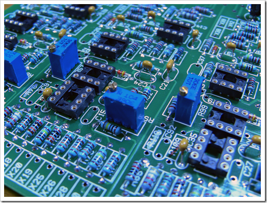
The next step was to solder yet more components to the board. I
soldered the trimmer potentiometers as well as a number of the
capacitors.
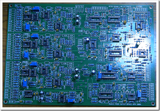
Over the next several months I'll be building what is definitely
my most complex electronics project to date: the MFOS (Music From
Outer Space)
Sound Lab Ultimate,
Ultimate Expander and (if Santa brings one)
Sound Lab Mini-Synth Mark II, likely all in the same home-made
wooden case, side by side. The Ultimate and Expander are together a
3 oscillator monophonic true analog synthesizer with filters,
envelopment generator, ring modulator, sample and hold and more.
You patch between the different logical modules using banana
cables, so it's a bit of a self-contained modular synthesizer. The
Mark II is smaller, newer, and has a few fewer features, but a
sound of its own. You also patch that with banana cables, and can
integrate the two. This blog post is another in the series.
Previous posts include:
Trim pots
The MFOS synthesizer uses multi-turn cermet trim pots to make
tuning the various parameters possible. I picked them up from Tayda Electronics. These are used throughout
the synthesizer to enable calibration.
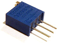
These are +/- 10% Cermet pots with a top-mounted multi-turn (25
I think) adjustment screw. Not for this board, but for the others,
I recall running into a case where I could only find the
side-mounted adjustment screw versions for at least one of the
values. Those will work too, but the adjustment screw may be more
difficult to access.
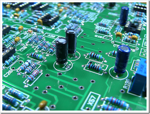
Capacitors
Pay attention to the build notes at the MFOS site. Ray has a few
substitutions you may wish to make, specifically swapping out some
of the Tantalum capacitors for aluminum electrolytic ones of the
same value.
One thing I didn't like about the board layout was that several
of the spots for the aluminum electrolytics were sized for a much
larger capacitor with 5mm leads. The smaller sized ones (of the
correct voltage and capacitance) work fine, but they stick up from
the board a bit rather than sitting flat. For grins, I tried
finding 5mm lead versions on Mouser, but those are almost
impossible to find. My guess is that Ray had much larger values
originally spec'd or something.
I ordered some additional capacitors from Mouser. It turns out I
was missing a few values. Those should hopefully arrive either just
before or just after Christmas. Once those are in, I'll be able to
calibrate the three oscillators. That's where the real fun begins :)
Other work
Based on feedback from the last post, I also replaced the
doubled-up 1/8W 3M resistors with single ones. Doubling up the
resistors in parallel actually decreased the resistance, and it
turns out the board won't need the full 1/4" watt ones anyway
(although those might be more heat stable). I'll keep an eye on
them in case heat becomes an issue.
Also, after pricing out the headers I'd need to make this board
easily disconnected from the panel, I decided to just pass and
instead wire the front panel directly to the board like everyone
else. I will, however, end up using coax for the mixer section as
Ray recommended in his MFOS Sound Lab Mini Synth Mark II build.
