In this post, I'm starting to populate the main board for my
MFOS Sound Lab Ultimate analog synthesizer.
Over the next several months I'll be building what is definitely
my most complex electronics project to date: the MFOS (Music From
Outer Space)
Sound Lab Ultimate,
Ultimate Expander and (if Santa brings one)
Sound Lab Mini-Synth Mark II, likely all in the same home-made
wooden case, side by side. The Ultimate and Expander are together a
3 oscillator monophonic true analog synthesizer with filters,
envelopment generator, ring modulator, sample and hold and more.
You patch between the different logical modules using banana
cables, so it's a bit of a self-contained modular synthesizer. The
Mark II is smaller, newer, and has a few fewer features, but a
sound of its own. You also patch that with banana cables, and can
integrate the two. This blog post is another in the series.
Previous posts include:
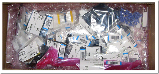
Yesterday, I received a huge (5lbs!) box of discrete components
from Mouser. If you think about the typical weight of components
like resistors and capacitors, and realize the box included no
solder, heat sinks, switches, potentiometers, or other heavy metal
objects, you can imagine that 5lbs of electronics components is
quite a bit of stuff.
Also today, I received my set of tempco (temperature
compensating) resistors from Precision Resistor Company (PRC).
They're not cheap at $4.50 each. However, if you want to have parts
of your voltage controlled oscillator (VCO) or other
temperature-sensitive components stay relatively stable after
warm-up, you need these or an alternate circuit. (My Moog Slim
Phatty has a different microprocessor-controlled tuning circuit
which is both more complex, and more error-prone than this
approach. However, when it works, it tends to be more stable)
I also have some resistors from MFOS, but because I later
realized I needed some for other synth module projects, I decided
to simply put in an order with PRC.
Normally, you want resistors which stay relatively stable
regardless of temperature, so most are designed to have very little
fluctuation (a
temperature coefficient of 100ppm or 50ppm for most 1%
resistors). A temperature-compensating resistor is one which is
specifically manufactured to change its resistance based upon its
temperature. It might have 3300ppm or 3500ppm, for example. You
stick one of these down right on top of the part that gets affected
by the heat so the two are at the same temperature, and then you
hook the leads into an appropriate place in the circuit.
I half expected the resistors to be individually wrapped like
little toffees. Ben (my 5yo son) said they look like Darth Maul's
light saber - he wanted to borrow some for his action figures.
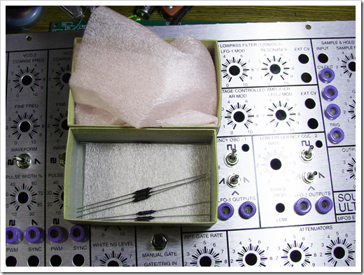
You can also see in the picture that I did a little bit of work
on the front panel installing half the banana jacks and several of
the switches. Because I'm still waiting for most of the parts for
that, I'll cover it in a different post.
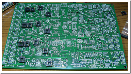
So, instead, I decided to start working on the main board.
I installed some of the IC sockets first. I've concentrated on
the three oscillator sections as I intend to test them before
moving forward to the rest. The sockets are machined pin, gold
plated sockets as Ray recommends. With something like an analog
synth, you want the best possible connections to your ICs.
Soldering them directly to the board would be the best connection,
but it's also the least flexible, and it's easy to destroy an IC
during soldering. You can get the cheaper dual-wipe IC sockets, but
the machined pin sockets are a lot kinder on the ICs if you remove
them; the dual-wipe kind can often bugger up the IC pins something
awful. The machined pin sockets are supposed to also have better
conductivity. The downside is the cost of the machined sockets
compared to the dual wipe kind - they're significantly more
expensive. Buying in quantity can help bring that cost down.
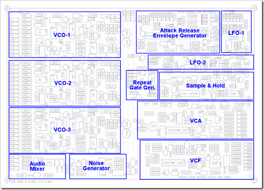
You can see the three oscillators called out in this diagram
from the MFOS site. They are located at the left side. Each
oscillator is identical. Also, each oscillator will need to be
tuned independently on the scope. I have a 5v/octave test board
from MFOS that I plan to use to help me out with that.
I also installed a number of the small signal diodes. You can
see two of them in this photo
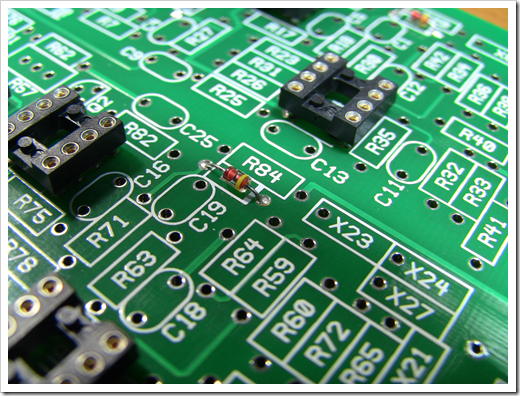
I eventually installed all of them and decided that when doing a
particular component value, I'd just do all of the board, but at
least focus on the components that are in the three
oscillators.
Here's the result of the 100k resistor install, which is an
exception as there are none in the oscillators. However, as the
most numerous resistor, I had to just go and plop them all in.
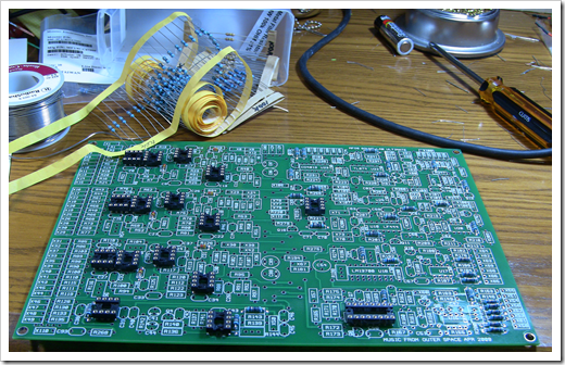
Here's the board with all the 100k resistors, all the IC
sockets, and all the small signal diodes in place. I'm following
one of Ray's latest modifications which exchanges a couple of the
100k resistors for some smaller values, so a couple of the slots at
the bottom right, which would normally have 100k, will have
different values.
I used 1% resistors simply because when buying in bulk, they're
just about the same price as 5% ($4 for 200 1% resistors 50ppm from
Mouser in most cases). If I'm going to stock up on resistors for
various projects, I'm going to stock up on 1%, not 5%. For this
project, I'll only have a few 5% ones at all. (Psst: I happen to
like the look of the blue 1% resistors too, but don't tell anyone I
said that)
That's probably all I'll do on this before I head to VSLive. I
do actually need to prep my presentations :). When I return, the
potentiometers and remaining banana jacks for the panel should be
in, so I'll likely continue with that in the next update.
