I have a few pieces of analog gear which either don't support
MIDI, or simply work better with voltage control. This makes
including them in a sequence difficult as timing of arpeggios or
sequences will drift away from the rest of the performance. Not to
mention that synchronizing them by ear is not a simple task in any
case, and impossible to do in real-time if you want to adjust the
tempo during the performance.
One such piece is my little Korg Monotribe. This is a
combination drum machine and step sequencer built into a very
inexpensive package.
The Monotribe doesn't have MIDI support (although you can build
a conversion for MIDI), but it does accept a sync pulse. The Aturia Minibrute doesn't send an analog clock
pulse, so there was no way to synchronize the two. However, the
Minibrute *does* accept MIDI clock pulses from an external source,
so I knew I could build on that.
Hybrid Analog/Digital sequencers like the Doepfer Dark Time will handle this
synchronization for you, but for a price. I already have one analog
sequencer on order, one small one mostly built, and another ready to be built, so I didn't want a third
one right now.
The Goal
So the goal is to drive both analog gear as well as more modern
MIDI gear from an external MIDI clock. In my case, I decided to use
Cubase 7 on my PC as the clock source. The completed setup looks
like this:
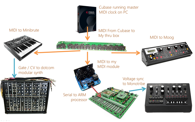
All the straight MIDI communication just works. The rest of this
post will focus on the development of the MIDI to analog sync
signal part. First, however, a little background on
synchronization.
MIDI sync
MIDI master clocks send out 8 bit synchronization messages at
the rate of 24 for every quarter note. At a typical BPM of 120,
that means that there are 24 * 120 = 2880 clock messages per
minute, or 48 clock messages per second.
The standard MIDI protocol itself is a 5v serial protocol
running at 31,250 bits per second with 8 data bits, no parity bits,
and 1 stop bit. Most messages are two or three bytes in length, but
a number of important messages, such as the real-time messages, are
only one byte in length. Also note that messages can be interrupted
by real-time messages. So, you could get the "note on" message, and
then the clock byte, and then the note on message's data. Any code
which parses these messages must handle this gracefully.
Analog Sync
Analog sync pre-dates MIDI clock signals, so there are a number
of standards. Roland used a DIN
sync for drum machines, TB-303, and others. This is a 5 pin
cable which looks like MIDI, but is actually carrying completely
different analog signals.
Even older than that is the modular approach of clock pulses.
This is typically a 5v square pulse which is used to move a
sequencer to the next step. This is the way most analog sequencers
synchronize with each other, all sharing a common clock/sync
source.
The Korg
monotribe is a new design, but follows older analog principles.
In this case, the sync signal doesn't need to be 5v. In fact, there
are phone apps which use audio level signals from the headphone
jack to generate sync pulses for the monotribe. Much like the
classic analog approach, the monotribe sync approach is used to
move the sequencer from one step to the next.
There are many other devices which can synchronize with signals
like this. For example, the Nova Drone drone synth includes LFO sync which
should work with this type of signal. (I haven't tried it yet,
though).
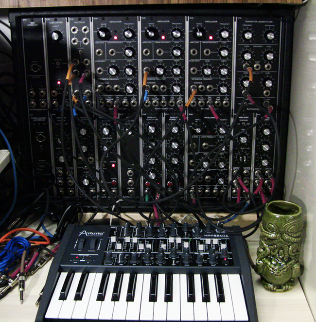
(Yes, that's a Cthulhu mug. I know I just floored you with the
awesomeness of this photo)
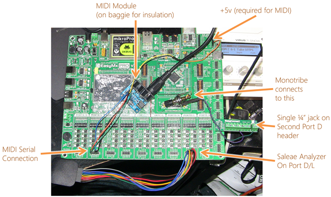
Implementation
I've done a fair bit with MIDI hardware, so I knew generally how
to parse messages and otherwise deal with the data. I also have a
MIDI module which, although designed for .NET Gadgeteer, includes
pins so I can use it with any microcontroller. Real-time processing
of MIDI messages like this has proven to be too intense for
interpreted code like NETMF, so I turned to my ARM development
board. Sure, this is something which could have been easily
accomplished on Arduino, but I've been getting into ARM lately, and
have had larger plans for the processor.
The development board I used is my Mikroelektronika EasyMX Pro v7 for STM32. the C
IDE is a mess compared to Visual Studio, but I can't praise this
board enough. It's super easy to develop and debug on it, all over
USB.
Because the monotribe runs perfectly fine on low amplitude
pulses, the 3.3v signal level from the ARM processor works fine. If
you use this approach with other analog gear, you'll likely need to
scale the output up to 5v (again, not an issue if you use classic
Arduino or AVR which both natively support 5v signals).
Initially, I based the pulses on 64 for some reason. I
originally thought MIDI used 64 pulses and not 24. Because
of this, the code below is not quite correct (it works,
but doesn't correspond to actual beats, so the divisions aren't as
useful as they should be).
#define MIDI_TIMING_CLOCK 0xF8

#define ANALOG_CLOCK_PULSE_DURATION_MS 1

#define MAX_TICKS 64;


// USART2 TX is PA2

// USART2 RX is PA3


#define GPIO_BASE           GPIOD_BASE

#define ODR                 GPIOD_ODR


#define SetAllPinsLow()     ODR = 0;

#define SetPins(pinMask)    ODR = pinMask


char _uartReadByte;


void main() {

    unsigned short currentTick = 0;

    unsigned short pinsHigh = 0;


    GPIO_Digital_Output(&GPIO_BASE, _GPIO_PINMASK_LOW); // Set pins as digital output


    UART2_Init_Advanced(31250, _UART_8_BIT_DATA, _UART_NOPARITY, _UART_ONE_STOPBIT, &_GPIO_MODULE_USART2_PA23);


    Delay_ms(100);                  // Wait for UART module to stabilize


    while (1) {

      if (UART2_Data_Ready()) {

         _uartReadByte = UART2_Read();     // read the received byte


         if (_uartReadByte == MIDI_TIMING_CLOCK) {           // if MIDI clock message


            pinsHigh=1;    // always output full clock on first pin


            if (currentTick % 2 == 0) {

               pinsHigh |= (1 << 1);


               if (currentTick % 4 == 0) {

                  pinsHigh |= (1 << 2);


                  if (currentTick % 8 == 0) {

                     pinsHigh |= (1 << 3);


                     if (currentTick % 16 == 0) {

                        pinsHigh |= (1 << 4);


                        if (currentTick % 32 == 0) {

                           pinsHigh |= (1 << 5);


                           if (currentTick % 64 == 0) {

                              pinsHigh |= (1 << 6);

                           }

                        }

                     }

                  }

               }

            }


            if (pinsHigh) {

               SetPins(pinsHigh);


               Delay_ms(ANALOG_CLOCK_PULSE_DURATION_MS);


               SetAllPinsLow();


               pinsHigh = 0;

            }


            currentTick = (currentTick + 1) % MAX_TICKS;

         }


      }

    }

}
I hate that K&R style of brace indentation, but like I said,
the IDE is a mess. If you deviate from that style of indentation,
the tabs and whatnot get really screwed up. In fact, they get a
little screwed up anyway. IDEs in the microcontroller world are a
long way from what we're used to for more mainstream
development.

Essentially, the code gets each incoming byte and checks to see
if it is a clock message. If so, it checks the current tick to see
where we are in the timing and then sets a bitmask to set the pins
on a port to high based on that step. It then sets the pins high,
sleeps for 1ms, then sets them low again.
When I ran the code, I looked at the pulses using my Saleae Logic 8
channel USB logic analyzer (something which is absolutely
indispensible for work like this) and, after some debugging, got
the right results:
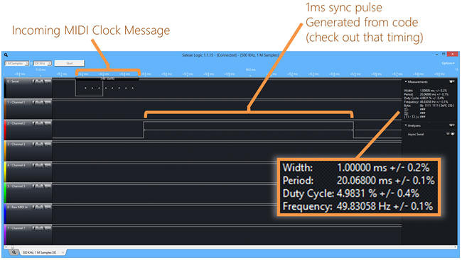
When you code this low to the metal, timing can be really spot
on. I love that!
Here's the full device setup on my mess of a desk:
And here's a full set of timing pulses, without the MIDI clock
signal visible:
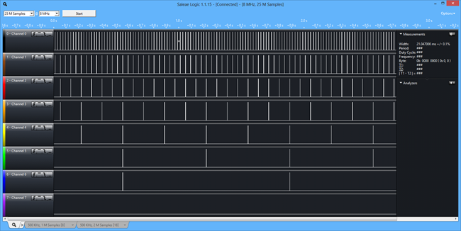
You can see that each row has a period twice that of the row
above it. By connecting to different signal divisions, you can
speed up or slow down the slave sequencer, but still keep it in
time with the rest of the performance. (Remember, I need to change
it to be based on 24, not 64 clocks per quarter note)
What's Next?
I'm going to correct the timing and then develop an inexpensive
board around this, possibly including support for TB-303/x0xb0x style DIN sync (including stop/start) in
addition to the analog sync. I'll keep a couple around for my
studio, but have others for sale. If you're interested, drop me a
line via the contact link here and let me know.
I'll also post a recording of the sync working on my
Soundcloud page.
Update: Recording is here:
https://soundcloud.com/psychlist1972/monotribe-and-modular-sync-test