Last year, I
designed my first Gadgeteer module. I didn't have a board
designed, but went through all the same steps. I recently designed
a MIDI module primarily for use with the .NET Gadgeteer, but also
for use with any 3.3v to 5v microcontroller with a serial port.
Existing MIDI boards all assumed a 5v signal level from the MCU.
Most modern MCUs are 3.3v or even less.
Having tried those 3.3v signals with MIDI equipment, I can tell
you the results were spotty at best. Some equipment was ok with it,
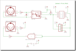
some was not. MIDI is a very old standard with poorly defined
specs. Rather than define minimum/maximum levels, they've simply
provided a reference
schematic.
Update 3/15/2012: A video of the
module in action (the first produced module, not the kit-friendly
module) can be seen on YouTube here: http://www.youtube.com/watch?v=PNeQ14DQbF0
What follows shows several different iterations of the board
design. The end goal was to stay under 5cm by 5cm in order to keep
cost down, and to make it suitably for hand assembly. I also
designed it from the start to be
Open Source Hardware and Open Source Software. I used the free
version of Eagle PCB to do the schematic and board layout.
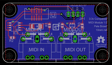
The first version turned out to be too wide. Being larger than
5cm bumped it into the next price range which is 150% the cost of
the 5cm price range. I decided that two mounting holes would be
enough as long as the MIDI connectors were well-soldered. Given the
number of solder pads they have, I figured they'd be ok. (For the
most recent version, I increased the size of the strain-relief
solder pads anyway.)
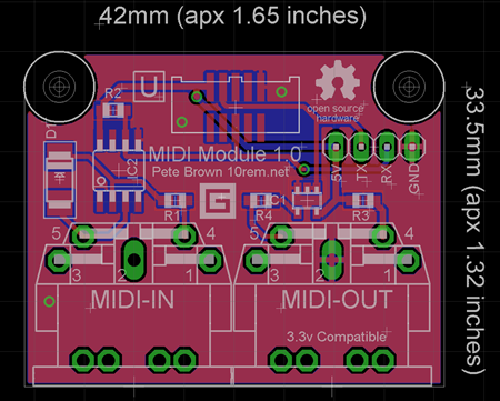
This next version is the first one I had manufactured. I created
my own MIDI connector footprint as the ones I was using were simply
too busy.
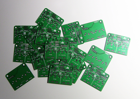
Here are the boards from Seeed. I ordered 20 of them.
My first board is also the first surface mount soldering I ever
did. Some of those parts are smaller than through hole solder pads.
Way too much flux on here, but at least the parts on working :)
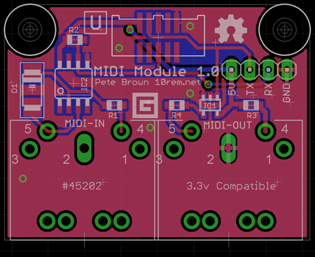
That board was ok except for one very important detail: the
footprint for the 6n138 opto-isolator was incorrect. It's way too
small on the board, and there is no 6n138 in that size package. In
order to keep prototyping I ended up having to do some ugly
soldering to get the isolator on to that footprint. I'm glad Seeed
charged very little for these boards.
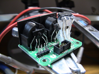
The one with the silicone on it was made for a friend in
Seattle. It has to survive shipping and handling. There's no way it
would have made it there intact if I didn't reinforce it somehow.
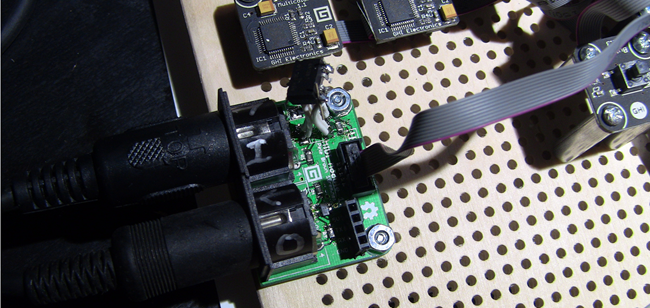
Here's mine, working on my dev board. I didn't clean any of the
flux off mine, as you can tell from this picture.
That version also used tiny SMD components. Those were ok for me
to solder, but many people shy away from surface mount for hand
soldering. I know I did until I tried it out.
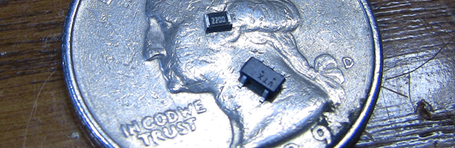
The board has four of those tiny resistors (marked 2200). As far
as surface mount goes, those are actually pretty huge. There's also
a surface mount diode, the opto-isolator and the Gadgeteer
connector. The board also has one surface mount 5 pin logic gate
which I use to convert 3.3v to 5v as required by MIDI. That's the
one surface mount ic that made it into the final version, as
there's no suitably small replacement component. The only other
surface mount bit that made it through is the Gadgeteer connector.
You can get those in through hole, but the surface mount version
actually seems a little easier to work with.
This first run also had one other flaw: the signal to the MCU is
pulled up to 5v. That works fine on the FEZ Spider (my test board)
and the Netduino and other 5v tolerant boards, but not with the FEZ
Hydra and others. In any case, the Gadgeteer spec only requires
pins be 3.6v tolerant, so I had to change the pull-up.
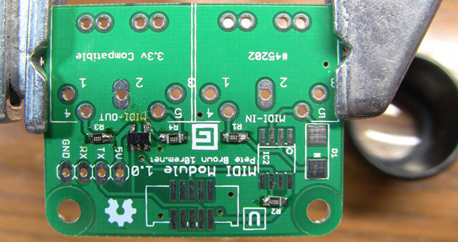
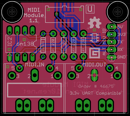
For the next version I decided to try out more through hole
construction. This will be much easier to provide to people as a
kit. I may pre-solder the logic gate and the gadgeteer connector,
but everything else is standard through-hole construction. The
board is slightly larger than the SMD version, but is still pretty
small. I also increased the size of the solder pads on the MIDI
connectors to make sure they weren't going anywhere.
I added the additional pin for the 3.3v reference supply for the
6n138. If you want only 5v signals coming and going, and you're not
using Gadgeteer, you can actually plug 5v into both 5v and 3.3v
"Alt MCU IO" pins.
For anyone who wants to get these fabricated themselves, under
the Open Source Hardware license, the current schematic and board
design files attached. For anyone else, I'll very likely end up
selling kits of this board in the near future. Expect an
announcement when that happens.
Also, here are the parts this is designed to use:
| Quantity |
Mouser Part |
Description |
| 1 |
863-M74VHC1GT08DTT1G |
ON semiconductor. TTL-level gate. |
| 2 |
806-KCDX-5S-N |
5 pin DIN PCB mount MIDI connector (these similar ones
from Sparkfun also work) |
| 4 |
270-220/AP-RC |
1/8w (small footprint) through hole
metal film resistor. 220 ohms. |
| 1 |
512-6N138 |
6N138 High Speed Optocoupler. DIP-8
package |
| 1 |
|
(optional) 8 pin DIP IC socket |
| 1 |
512-1N4148 |
1N4148 through hole small signal diode
(any manufacturer is fine) |
| 1 |
Get
through GHI |
10 pin Gadgeteer Socket |
| 1 |
Get
through GHI |
Gadgeteer 10 pin flat ribbon
cable. |
| 1 |
|
Optional 5 pin header (male or
female). Standard .1" spacing. |
Please keep in mind I haven't yet assembled one from this round
(they'll arrive in around two weeks). Depending on the processor
you work with and the voltage levels, the value for R2 (the
pull-up) may need to be adjusted. 220 is typical, but I've seen it
at 470 and even as high as 10K. Current size works fine with the
FEZ Spider board. I'll test with other main boards once I get the
new PCBs in.
I'm working on the driver and have an early version of it
completed. It's not up in source control yet as I need to figure
out if I'm going to host it as part of the Gadgeteer CodePlex
source or something else. I plan to cross-compile this to Netduino
as well. If you're getting your own version of this fabbed and need
access to the WIP driver code, just drop me a line.
You can see the full development of
this board and driver, including all the great help I got by
developing this in the open, in this thread at
TinyCLR.com.
I have a number of other modules in mind. This stuff is fun
:)
