The Gadgeteer has turned out to be a great and exciting new
platform for .NET Micro Framework developers. It makes it very easy
to use existing modules to prototype a product, or just do fun (and
useful) projects. However, I'm not a fan of close systems; if the
Gadgeteer was closed and didn't easily allow extending, I wouldn't
be into it. Happily, that is not the case.
As a part of some of my longer-term projects, I'm considering
using the .NET Gadgeteer as the heart of something interesting.
That would require designing at least one, probably three or so,
different custom modules. Designing a module for the Gadgeteer
includes several different components, so I thought I'd try a very
simple one here.
As in the introductory "Getting Started with the .NET
Gadgeteer" post, I'm using the GHI FEZ Spider, a great .NET Gadgeteer kit.
One document I'll refer to a number of times during this post is
the .NET Gadgeteer Module Builder's Guide. This
document has a great amount of detail interesting not only to
module builders, but to people who just want to understand the
details of how the Gadgeteer works. If nothing else, I found the
Socket Types Table very useful.
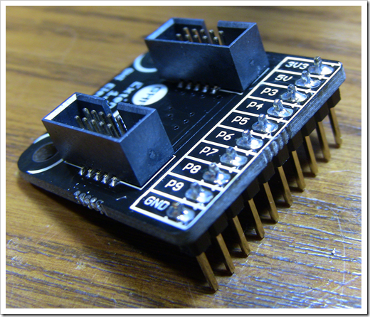
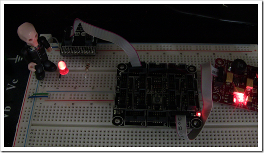
The GHI FEZ Gadgeteer Breakout Module
The Gadgeteer spec standardized on a 10 pin male plug for all
connections. The plug is tiny and is not breadboard-friendly.
However, GHI makes a breadboard-compatible breakout board called
the Extender Module; all you need to do is solder
on some header pins (not included) and you're good to go. Here's
mine with the pins soldered:
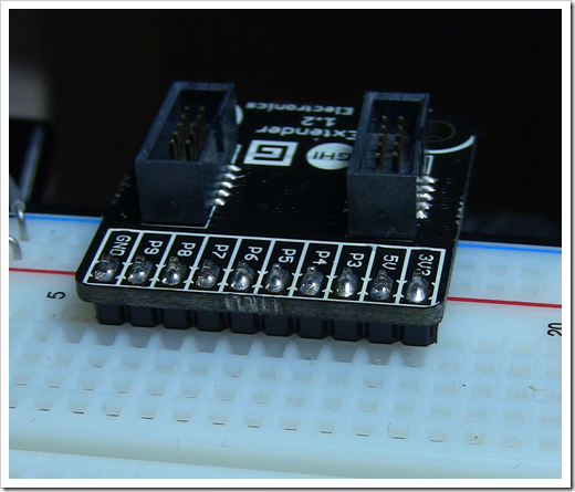
And here it is shown plugged into the breadboard. It doesn't
take up much room at all.
Creating the Module Circuit
The module I've decided to create is a very simple LED module.
This has a single regular old LED which can be switched on or off
via data sent from the pins. Why an LED module? It's about the
simplest circuit you can create which does something obvious with a
digital signal.
GPIO (General Purpose Input/Output) pins on the Gadgeteer are
3.3v digital pins. Typically, you don't want to hook an LED
directly to a power source (even a digital one); it's best to put
in a current-limiting resistor. I chose 100ohms as I had one handy,
but even 50ohms would be fine for a standard red LED like what I'm
using. Larger values will work as well, but the LED will be dim;
too high a value and you may not notice it light up.
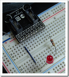
Test Circuit
The first thing to do is to create a test circuit. This will be
identical to the final circuit with one exception: instead of
wiring to one of the GPIO pins, I wired it directly to the 3.3v pin
on the extender board. Make sure you're using the 3.3v pin, not the
5v pin, otherwise the results won't look like what we'll have in
the final circuit.
Now, plug the the extender board (either socket) into an X or Y
socket on the Gadgeteer. I chose socket 14. Then, plug the power
module into the main board (socket 1 on the Spider) and plug the
whole thing into a power source. I simply plugged the USB cable
from the PC into the board.
You should immediately see the LED light up. If it doesn't, make
sure you've plugged the anode (long leg) into the +3.3v output of
the breakout via the resistory, and the cathode (short leg) to
ground. If it still doesn't work, consider trying out a different
LED, as the one you're using may be toast.
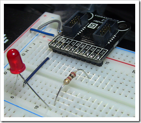
Final Circuit
The next step is to remove power from the board and plug the LED
(again, via the current-limiting resistor) into the P3 pin of the
extender module.
Plug the Gadgeteer back into USB and verify that the LED is not
lit up. If it is lit up, double-check your connection. If the
connection is fine, you may actually have a program still loaded on
the Gadgeteer which happens to use that pin - no worries.
Deciding on the Connection Type
The Module Builder's Guide has a great table which shows the
different socket types. I've reproduced that below. However, always
refer back to the official documentation in case it changes in the
future.
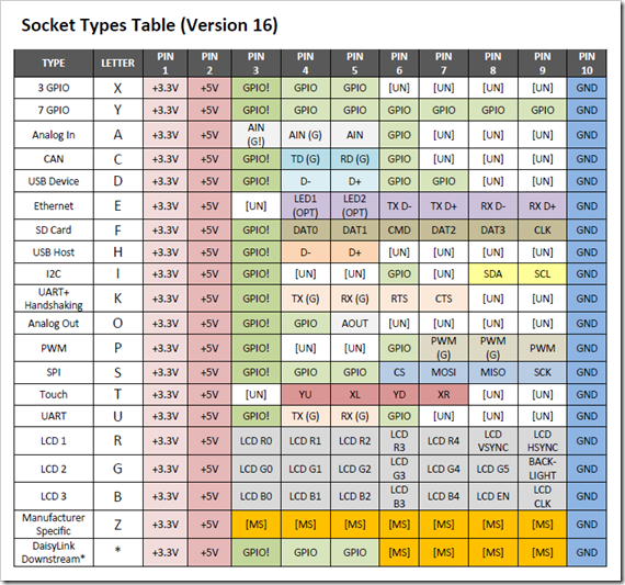
Most every socket supports GPIO on Pin 3. As indicated in the
documentation, a module which is so simple that it can work on
multiple different types of sockets should list XY because most
mainboard sockets are XY compatible. So, for our little BlinkenLED
module, we'll use XY as the socket type.
Creating the Module Driver
On the Gadgeteer CodePlex site there is a set of .NET
Gadgeteer Builder Templates. We'll need that to build our own
module, so go ahead and install them now. The MSI installs three
main templates: the .NET Gadgeteer Module, the .NET Gadgeteer
Mainboard and .NET Gadgeteer Kit. We'll be using the module
template.
Project Setup
Modules in .NET Gadgetter should/must follow the standard naming
convention of GTM.<manufacturerName>.<moduleName>.
However, the template makes the assumption that you'll name
the project only with the "moduleName". If you follow my usual
approach of naming the project the full assembly name, you create a
lot of other search and replace work for yourself.
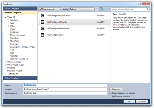
Therefore, create a new Gageteer Module project named simply
DerBlinkenLed as shown here:
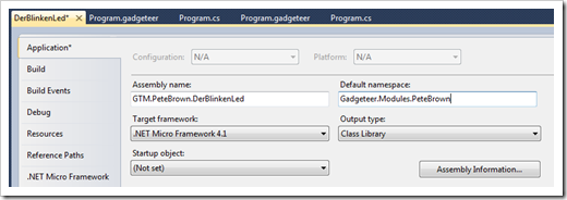
Of course, you should change "PeteBrown" to be your own name or
company name. Now, because the project/assembly name is not quite
the same as the namespace you want to use (it's shorter to help
avoid long path issues), the first thing to do in the project is
update the project properties with the correct namespace.
You'll notice the default assembly name in the project
properties has
GTM.ManufacturerName.<whateverYourProjectNameIs>. Change the
assembly name and default namespace so "ManufacturerName" is your
company name. In my case, I changed it to "PeteBrown". The final
values are shown here:
The ReadMe.txt that comes up when you create the project has a
few other steps you'll want to follow. We just completed step 1,
changing the ManufacturerName in project properties. Step 2 says to
do a quick search and replace across the entire solution (skipping
the ReadMe file) as shown here:
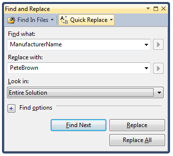
This will replace values in the configuration file, assembly
info, and the .wxi installer file.
Der Module Driver Code
The module driver file "DerBlinkenLed.cs" includes a great
template with comments to help you get started. It's
sensor-oriented, but it lets you see the structure. Our blinking
LED module, however, will simply blink an LED at a specified rate,
so we'll ditch most of the code. Here's the proposed API:
| Member |
Description |
| Blink |
Blink the LED at the specified rate.
It takes a single TimeSpan parameter named "interval" which is used
to control how long the LED stays on and how long it stays
off. |
| StopBlinking |
Stop blinking the LED. Turn it
off |
The code for the module is as follows:
using System;

using Microsoft.SPOT;


using GT = Gadgeteer;

using GTM = Gadgeteer.Modules;

using GTI = Gadgeteer.Interfaces;

using Gadgeteer.Interfaces;


namespace Gadgeteer.Modules.PeteBrown

{

    /// <summary>

    /// A LED module for Microsoft .NET Gadgeteer

    /// </summary>

    public class DerBlinkenLed : GTM.Module

    {

        Socket _socket;

        DigitalOutput _output;

        bool _ledState = false;

        Timer _blinkTimer;


        /// <summary></summary>

        /// <param name="socketNumber">The socket that this module is plugged in to.</param>

        public DerBlinkenLed(int socketNumber)

        {

            _socket = Socket.GetSocket(socketNumber, true, this, null);


            // For the LED, we'll use a digital output on

            // pin 3 of the specified socket

            _output = new DigitalOutput(_socket, Socket.Pin.Three, false, this);

        }


        /// <summary>

        /// Begin blinking the LED

        /// </summary>

        /// <param name="interval">Time span for on time and for off time.

        /// For example: if set to one second, LED will be on for one second

        /// and then off for one second

        /// </param>

        public void Blink(TimeSpan interval)

        {

            // if timer was already running, unhook the event handler

            if (_blinkTimer != null)

            {

                _blinkTimer.Tick -= OnBlinkTimerTick;

                _blinkTimer = null;

            }


            // calculate milliseconds from the provided timespan

            // the NETMF version of Timespan lacks the TotalMilliseconds

            // property as well as a few others

            int totalMilliseconds = (int)(interval.Ticks / TimeSpan.TicksPerMillisecond);

            _blinkTimer = new Timer(totalMilliseconds);


            // wire up new event handler and start the timer

            _blinkTimer.Tick += OnBlinkTimerTick;

            _blinkTimer.Start();

        }


        private void SetLedState(bool newState)

        {

            _ledState = newState;


            // write the new value to the pin

            _output.Write(_ledState);

        }


        private void OnBlinkTimerTick(Timer timer)

        {

            // reverse LED state

            SetLedState(!_ledState);

        }


        /// <summary>

        /// Stop blinking the LED and return its state to "off"

        /// </summary>

        public void StopBlinking()

        {

            if (_blinkTimer != null)

            {

                // unhook event handler

                _blinkTimer.Tick -= OnBlinkTimerTick;


                // stop the timer

                _blinkTimer.Stop();

                _blinkTimer = null;

            }


            // turn off the LED

            SetLedState(false);

        }

    }

}
In those code, you can see I created a digital output based upon
the socket provided by the calling code. The digital output is on
pin 3, just as used in our circuit. Then, when the calling code
calls the "Blink" method, I start a timer which
The Test Project
In the same solution, create a new Gadgeteer Application named
"TestDerBlinkenLed". Immediately add a project reference from that
to the DerBlinkenLed project.
We won't use the design surface yet, because we haven't yet
built that part out. Instead, we'll create the LED module instance
from code.
using System;

using Microsoft.SPOT;

using Microsoft.SPOT.Presentation;

using Microsoft.SPOT.Presentation.Controls;

using Microsoft.SPOT.Presentation.Media;


using GT = Gadgeteer;

using GTM = Gadgeteer.Modules;

using Gadgeteer.Modules.PeteBrown;


namespace TestDerBlinkenLed

{

    public partial class Program

    {

        private DerBlinkenLed _led = new DerBlinkenLed(14);


        void ProgramStarted()

        {

            // Do one-time tasks here

            Debug.Print("Program Started");


            // blink for one second on, one second off

            _led.Blink(new TimeSpan(0,0,1));

        }

    }

}
Set the TestDerBlinkenLed project as the startup project and run
it. After the deployment, you should see the LED start to blink.
Once you stop the project, the LED will continue to blink because
the code on the Gadgeteer continues to run…forever. If you want to
stop the blinking, replace the _led.Blink line above with a call to
_led.StopBlinking(), and re-deploy the application.
Creating the Design Surface and Configuration
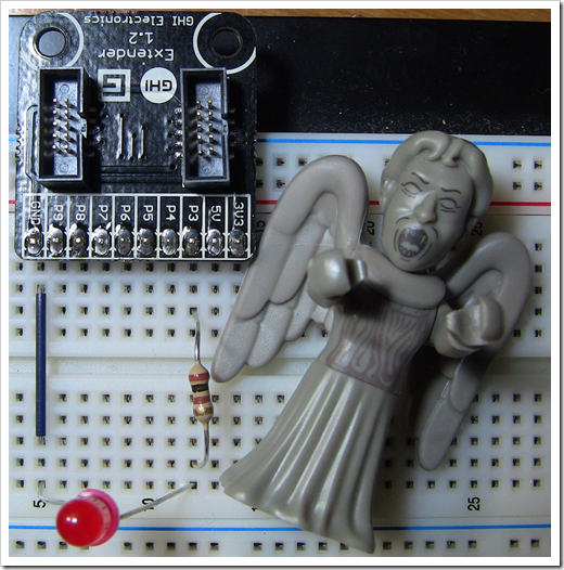
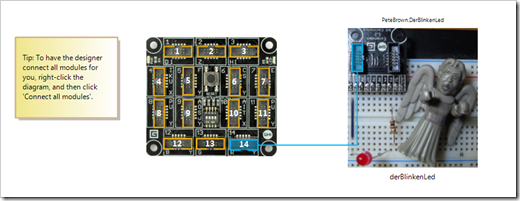
Now we get to the fun part! Time to take a picture of your
wonderful creation, and use it as the diagram. Typically you'd use
some high-quality photograph of your board, but since this is a
breadboard, I'm just using any old snapshot. I decided to use the
one with the extender board up at the top and the weeping angel
("don't blink") on the right.
Here's where being raised on the imperial measurement system
bites you a bit. All designer values are provided in MM, not in
pixels or in inches. So, we'll need to measure the board, and then
figure out the location of the socket from the top left. The
designer does the rest. Normally, with a real circuit board, this
is trivial. On a breadboard, it's slightly more complex.
Oddly enough, I don't have a single metric ruler around here. I
really need to fix that. With some inch measuring and a little Bing
conversion (type "convert 5 inches to mm" for example), I estimated
the values to be:
| Property |
Value |
| Board Height |
61mm |
| Board Width |
57mm |
| Socket Left |
4mm |
| Socket Top |
13mm |
I ignored the second socket on the board. The scaling will be
off because my estimated measurements are, well, estimates. In any
case, the image you provide should be high resolution; Visual
Studio will take care of scaling it to the same scale as the other
images based upon the measurements you provide.
Add the new image to the project in the resources folder, and
set its Build Action to "ResourceFiles"
File Name Note
I had to name my new image Image.jpg. When I left the old Image.jpg
in there and had a second one named LedBoardImage.jpg, even with
the correct entry in the XML file and the correct build action, it
wasn't found at design time. Only when I renamed it Image.jpg did
the design surface work. There's some setting somewhere that is
relying on that (or which doesn't like two images in the same
project), but I haven't yet found it. Until I figure that out, it
means one image and therefore one module per assembly, which is the
intent anyway.
Building the Installer and Testing the Design Surface
I haven't yet figured out a way to test the design surface
without building the installer in release mode; simply customizing
the toolbox to include it didn't work, and it doesn't automatically
appear in the toolbox when the project is in the solution. This can
be a bit tedious, but luckily the designer is only a small bit of
the functionality of the overall module.
To build the installer,first double-check the values in
common.wxi all look good (version, module name, manufacturer name
etc.). You don't need to worry about coming up with new GUIDs, the
ones in the file were generated when the template created the
project.
Then, switch the DerBlinkenLed project to Release mode.
Finally, build the project. If all goes well, you should get a
message saying the project built successfully.
Getting a WiX Error where it can't find the
DLL?
Chances are, you don't have the Windows Installer XML (WiX)
toolset installed. It's not something that's installed as part of
Visual Studio or the Gadgeteer tools. Luckily, this is a free
download from CodePlex. Exit Visual Studio and install the latest
version of WiX from http://wix.codeplex.com/
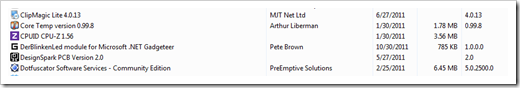
Look in the Release folder for the module project. On my
machine, that's
D:\Documents\Docs\Projects\DerBlinkenLed\DerBlinkenLed\bin\Release.
You'll see an Installer folder with the setup files included. The
setup project creates both a full MSI installer as well as a MSM
merge module which you can use when your module is part of a larger
project.
Close Visual Studio and run the MSI. The installer is very quick
with no options. You can verify installation by checking the
control panel programs list.
Open up the solution in Visual Studio and open the
Program.gadgeteer designer in the TestDerBlinkenLedDesigner
project. Sometimes the toolbox takes a moment to catch up. Once it
has, check to see if your module is there.
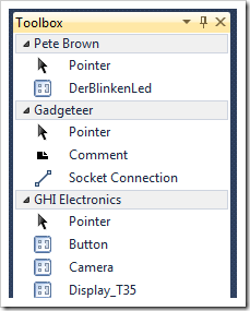
Drag a copy of DerBlinkenLed on to the design surface and try it
out. You should see your image. Right-click the design surface and
select "Connect All Modules" to automatically connect your new
module with the Gadgeteer Main module.
Then, to use it, simply rework the previous code to use the
design-surface version. Here's the new listing:
using System;

using Microsoft.SPOT;

using Microsoft.SPOT.Presentation;

using Microsoft.SPOT.Presentation.Controls;

using Microsoft.SPOT.Presentation.Media;


using GT = Gadgeteer;

using GTM = Gadgeteer.Modules;

using Gadgeteer.Modules.PeteBrown;


namespace TestDerBlinkenLedDesigner

{

    public partial class Program

    {

        void ProgramStarted()

        {

            // Do one-time tasks here

            Debug.Print("Program Started");


            // use our awesome custom LED blinking module

            derBlinkenLed.Blink(new TimeSpan(0, 0, 1));

        }

    }

}
Build it. Deploy it. Run it. You should see the same blinking
LED as before.
What Next?
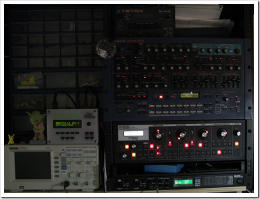
Now I need to create my first really functional module. What
will it be? I'll give you a hint: It has something to do with one
or more things in this photo:
The full solution is attached below.