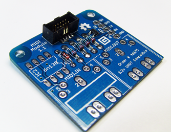
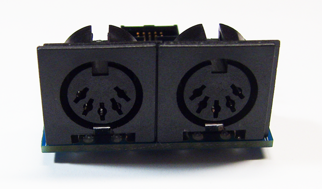
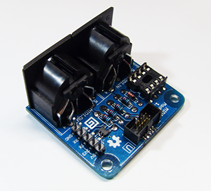
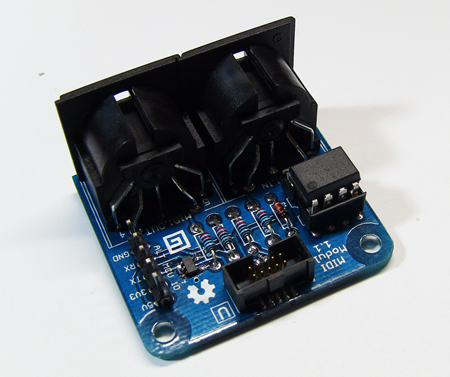
This module implements a basic MIDI In and MIDI Out interface
for 3.3v to 5v microcontrollers. MIDI is a 5v protocol, so special
steps were taken to step up the voltage on output, and step it down
(if 3.3v board) on input. This module includes a specific .NET
Gadgeteer-compatible 10 pin connector for use with .NET Gadgeteer
mainboards and the
Netduino Go, as well as a 5 pin .1" standard header for use
with other boards such as the Netduino classic, Arduino, AVR, FEZ Panda and
others.
If your board is a 5v board, expecting 5V signal levels
on inputs, tie the +3.3V and 5V lines together to the 5V
source.
Update 4/2/2012: Ordering information
is now at the bottom of this post for kits as well as for
fully assembled modules.
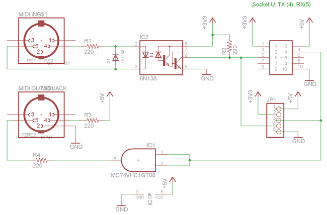
Schematic and Board Layout
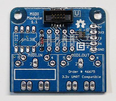
Following standard MIDI interfacing practices, the board uses an
optoisolator (a 6N138) to help prevent ground loops on MIDI IN.
Note also that the MIDI IN Jack is not grounded to the board. This
is also per MIDI specifications.
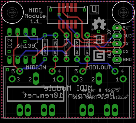
Blue traces are on the bottom of the board, red are on top. Both
layers are flooded with a ground plane so you won't see any of the
ground traces here.
R2, the pull-up resistor, is explicitly labeled on the
silkscreen using "PU". I have found 220ohms to work fine with the
boards I've tested it with. If you're trying a board with different
pin characteristics or pull-up requirements, you may want to use a
different value, such as 470ohm, or even as high as 10k.
Parts List
If you decide to have the board made yourself, you'll need a
number of parts. I've included links here for each of the required
components.
| Quantity |
Part (via Mouser unless
otherwise mentioned) |
Description |
| 1 |
863-M74VHC1GT08DTT1G |
ON semiconductor. TTL-level gate. |
| 2 |
806-KCDX-5S-N |
5 pin DIN PCB mount MIDI connector (these
similar ones from Sparkfun also work) |
| 4 |
270-220/AP-RC |
1/8w (small footprint) through hole
metal film resistor. 220 ohms. Typical 1/4w are slightly too big
for the board. |
| 1 |
512-6N138 |
6N138 High Speed Optocoupler. DIP-8
package |
| 1 |
|
(optional) 8 pin DIP IC socket |
| 1 |
512-1N4148 |
1N4148 through hole small signal diode
(any manufacturer is fine) |
| 1 |
Get through GHI |
10 pin Gadgeteer Socket |
| 1 |
Get through GHI |
Gadgeteer 10 pin flat ribbon
cable. |
| 1 |
|
Optional 5 pin header (male or
female). Standard .1" spacing. |
| 1 |
MIDI Module PCB Board |
From me, or have manufactured
yourself |
Of all the pieces, the key ones not to substitute are the ON
Semiconductor TTL-level gate, and the 6N138. The TTL gate is used
for level shifting a 3.3v signal to a 5v signal for MIDI out. This
is required to support 3.3v MCUs. I haven't found a suitably small
through-hole version. Most are 14pins or more, making the board
much larger than it would need to be.
The 6N138 has been tested and has proven itself again and again
as the most compatible of all optoisolators. MIDI equipment can be
old and therefore very finicky. I do not recommend substituting
this part, but as it is socketed, you can try others if you
wish.
Here are the parts that make up the assembly:
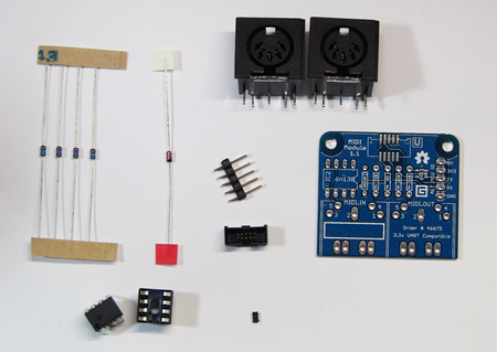
The parts may look slightly different, but will be equivalent
(for example, some of the 1n4148s I have have slightly shorter
leads). Not shown is the Gadgeteer 10 pin flat ribbon cable. The
tiny part is not a tick, it's the ON Semiconductor TTL gate.
Unless you explicitly request otherwise, this will already
be soldered to your board when you get it.
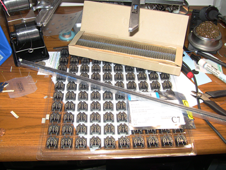
That's a shot of the first round of parts for this kit. An ammo
box of 220ohm 1/8w resistors, a tube of optoisolators, a tray of
MIDI connectors, and a tape of TTL logic gates.
Tools Needed
If you've soldered boards in the past, you should have
everything you need. Here are my recommendations:
- Soldering iron. Preferably one with a good temperature control.
The Hakko FX888 gets great reviews. I have a Weller WESD51 with a small screwdriver/flat
tip. My dream setup would include a Hakko FM203 with two different irons.
- Solder wick to help with any screw-ups.
Optional, but helpful. If you buy some, get the good stuff, not the
cheapo wick. Cheap wick burns your board more than helps.
- Solder. I use Kester 66/44 .020" RA rosin-core for soldering
all but the largest components, and the .031" stuff for the bigger components.
Whatever you're used to using should work, but I strongly
discourage using big fat solder wire.
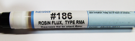
- Optional: I've found that a rosin flux pen helps with the
surface mount connector and the TTL logic gate. Use a flux that is
compatible with your solder. I use Kester #186.
- Optional: Flux cleaner. Rosin-core flux can be left on the
board after soldering. It's not super pretty, but it hardens into a
plastic-like substance that keeps the acids locked up. If that
still bothers you, before you put the optoisolator chip in place,
you can use a good flux cleaner on the board. There are any number
of them that will work. Here is one. Clean in a well-ventilated area,
and make sure the board is completely dry before you apply any
power.
- Side cutters for trimming the leads.
- Optional: Tweezers.
Knowledge is Power
If you haven't soldered before, or you haven't soldered much, I
highly recommend the following soldering tutorials by Dave at the
eevblog. Watch them before continuing.
Soldering
tutorial: Parts overview. Good to watch if you are just starting
out.
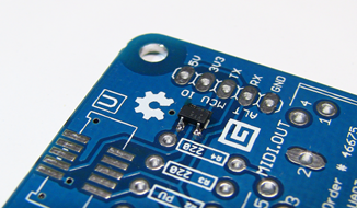
Step 0: The TTL Logic Chip
The first step is to solder the TTL Logic chip. Unless
you've requested otherwise, this will already be on the board when
it arrives.
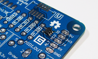
When soldering little guys like this, I usually wear a
magnifying visor and hold the chip in place with a pair of
tweeters. I then bring a tiny blob of solder over to one of the
pins just to tack it in place. I then, using a tiny bit of solder,
fix each other pin in place before returning to the tacked pin to
clean it up. Don't heat this guy up too much. Also, be careful not
to lose this tiny part. I don't have spares, but you can get them
via Mouser using the link in the parts list.
Take a look at the schematic and the board layout. Two
of the three pins closest to the ALT MCU IO header are supposed to
be bridged. Looking directly at the three pin side, the
left two are the ones that should be bridged. They may be bridged
just at the circuit board level, or both at the pin and board
level. Either is fine. Why bridged? That's because I use this AND
gate as a simple voltage translator. Bridging the two inputs
means 1 AND 1 = 1 and 0 AND 0 = 0.
Make sure each of the pins has a good connection with the board
and other than the noted pins, none of the others are bridged.
If this chip is not soldered correctly, MIDI out will not
work.
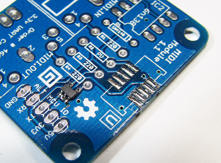
Step 1: The Gadgeteer Socket
The next component to solder is the Gadgeteer socket. If you're
not using this board with the .NET Gadgeteer, you don't have to
worry about soldering this socket.
This is a surface mount component, but it has fairly large pins,
and I've extended the pads to make it beginner-friendly. In any
case, an eye loupe, magnifying glass, or magnifying visor will come
in handy when checking the connections here.
The notch on the socket points inward to the resistors and the
rest of the board.
Update 4/16: I have a
more thorough tutorial for soldering these sockets now avaialable
on my blog here.
If you have a flux pen, put a little flux on all 10 pin pads as
well as on the bottom of the socket pins themselves.
I've found, for first-timers, the easiest thing to do is
to melt a tiny blob of solder on to the iron tip, and then rub it
across ONE of the 10 pins here to tin it. You'll end up
with a little mound of solder on that one pad. In the photo below,
I tinned all 10 pads. This is what I used to do. You can use
this approach, but after assembling a bunch of these, I've found it
much more difficult to keep the socket aligned. Tin just
one pad for the easiest assembly.
Then, holding the socket in place so that it lines up with the
silkscreened outline, press down on the one one pin to melt it on
to the tinned pad. This will tack everything in place. Ensure the
pins are all lined up. If not, heat that one pad and try again.
A small iron tip helps here.
Once everything is aligned, heat each pin and pad and solder
them so the solder just covers the pin. Be sure to go back and get
that first pin to make sure it has a good solder connection.
Remember, you not only need a good electrical connection here,
but also a good physical connection. This socket takes a fair bit
of abuse.
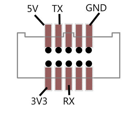
If you have a multimeter and want to do a continuity
test to check your soldering, put one probe on the pin in
the connector and the second probe on the labeled header pad on the
right of the board. You should find the pins as follows. (Oriented
just like the board in the photos. Mounting holes at the top)
Double-check your joints here, preferably with a magnifying
device of some sort. it's really easy to have a pin sitting on top
of the pad instead of soldered to it.
With that, all the hard stuff is done. Everything else is
traditional through-hole construction from this point forward.
Step 2: The Diode
Next up, the diode. Diodes are polarized. That is, the direction
in which you install them is important. One end of the diode will
have a black line (more likely a smear). Align that with the white
line on the silkscreen as shown in this photo.
Quickly solder the diode. You don't want to linger and burn it
up, but you don't have to race either. Make sure you get enough
solder on so you have a nice small but correctly shaped fillet on
the bottom as well as on the top. A proper solder joint should look
like the double-sided PCB example shown here (board is upside down
in the diagram)
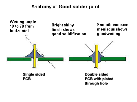
(the image links to the source. There are lots of soldering
tutorials out there. Refer back to the ones in the opening if
you're not sure.)
Snip off the excess lead, being careful not to cut into the
solder fillet itself.
Step 3: The Four Resistors
There are four 220 ohm 1/2w resistors. These are a smaller size
than the usual 1/4w resistors you may be used to, but they solder
exactly the same way. There's one resistor, R2, which is marked on
the silkscreen as a pull-up. 220ohm has worked for every board I've
tested, but if your microcontroller needs a stronger pull-up,
replace that with a 470ohm or even 10k ohm resistor as required.
Get the 1/8w smaller ones if you can, as the larger 1/4w resistors
won't quite fit without putting them in a bit crooked (and we don't
pass anything close to 1/4w anyway).
Resistors are not polarized; you can put them in in any
orientation, but your board will look more professional if the red
lines all line up :)
That's it for all the low-profile components. The next step is
the IC socket for the optoisolator.
Step 5: IC Socket for the Optoisolator
You could solder the optoisolator directly on to the board, but
these are sensitive little guys. Inside, there is an LED and a
couple transistors, none of which would be good to fry. These chips
also cost almost a dollar each in large quantities, so it's better
to use a socket.
Orient the socket so the notch is lined up with the notch on the
silkscreen (pointing right in the photos below)
The next step is helpful if you will be debugging or using the
board with non-Gadgeteer devices.
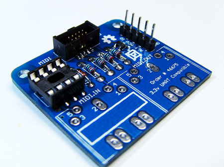
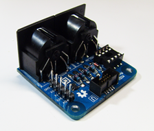
Step 6: Optional Breakout Pins
Install the 5 pin header. The easiest way to do this is to use
your thumb to hold the pin header to the board while it is flipped
over. Keep your thumb away from one of the end pins. Bring a blob
of solder to the pin your thumb isn't touching, and tack it to the
bottom (wipe the solder across the pin and pad), making sure the
pin header is perpendicular to the top of the board. If all looks
good, solder the remaining pins and then go back and fix up the
solder joint you tacked.
Next up: the final soldering step. MIDI sockets.
Step 7: MIDI In and Out Sockets
We're just about there! Next, put the two MIDI sockets on the
board. They should fit tightly with the faces overlapping at the
little notch. These should stay in place with just friction, so no
need to tack them in place unless you managed to get a socket with
undersized pins.
Use a fair bit of solder on these pins. MIDI sockets take a lot
of physical abuse. Take care to make sure, at least on the ground
and data pins, that you have good solder fillets both on the bottom
and the top. The solder pads nearest the edge of the board are
there just to help take the stress of insertion and removal.
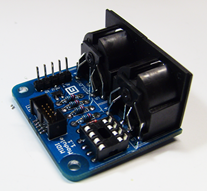
Step 8: The Optoisolator
The final hardware step is to insert the optoisolator chip. Line
the side with the dot or notch with the notch on the silkscreen and
the socket. In most cases, you'll need to bend the pins inward a
little before inserting it in the socket. The easiest way to do
this is to grab the chip by the ends and slightly roll it on a hard
surface like a table top. Don't over bend, but make sure the pins
will go cleanly into the socket.
Also, the optoisolator is a static-sensitive device, so no
scuffing around on the carpet while you mess with this chip!
You're done! The next step is to load up the software and sample
program and try it out on your own device.
Troubleshooting
MIDI In doesn't work
- Check Gadgeteer socket (continuity test as described above is
easiest way)
- Optoisolator socket not properly soldered, or chip not
correctly inserted
- Check resistor solder joints
- Check MIDI Input socket solder joints (remember, they need to
have a bead that extends to the top of the board)
- Diode in backwards
- Diode burnt out
MIDI Out doesn't work
- Check Gadgeteer socket (continuity test as described above is
easiest way)
- Check MIDI Input socket solder joints (remember, they need to
have a bead that extends to the top of the board)
- TTL Logic chip not properly soldered
- Check resistor solder joints
- TTL Logic chip burnt out (unlikely, but possible)
What to use it with
Wait. You don't have any MIDI devices in your
studio/office/garage? Check out some of these inexpensive, but very
cool, kits and sound modules.
Pricing Ordering Information
NOTE: As of 5/9/2014, both the kits and assembled
modules are out of stock. If there is sufficient interest for
another run, I will do so. Please email me with any questions or
suggestions. Also, if there's interest, I'm considering building
more functional and intelligent MIDI interfaces which include
things like timing/clock on-board, so they aren't affected by
.NETMF timing considerations.
The kit is $16 for the kit with a Gadgeteer socket
connector.
Shipping -- I always use current USPS rates. At the time of
writing, they are:
- Boxed Priority mail shipping anywhere within the US is a
flat $5.80. (I can fit several kits in the same box for the
same flat shipping fee, should you want more than one.)
- Canada and Mexico ship USPS Priority, boxed for
$19.95.
- All other countries are $23.95, USPS Priority, boxed.
Fully assembled modules are $26 plus the same
flat rate shipping. These take just a little bit longer to send out
to you, and may or may not use a chip socket (I may substitute an
SMD version of the optoisolator, at my discretion)
You probably already have spares, but add $2.50 if you want a
10cm Gadgeteer ribbon cable. I just get these
from GHI in packs of 10, and sell them at cost as a
convenience. Depending upon my own stock, this may add a slight
delay to the order.
Payment via PayPal. (I'll send you the paypal address when you
contact me)
Contact me if
interested.
Module Drivers, Source Code, Schematics and More
All the driver code, installer, board layout files and more are
available on my CodePlex site: http://petebrown.codeplex.com/