When creating modules for the .NET Gadgeteer or Netduino GO, one of the harder
parts to source is the 10 pin IDC socket. This is the tiny 1.27mm
pin pitch socket you see on the boards.

Manufacturers will get those by the reel in most cases, directly
from China. There are several places the average hobbyist can get
them from:
All of these sockets are black. The Netduino blue sockets were a
custom run by them, and so are not available to us mere mortals
:)
Sockets may come in tape, tube, or loose. In a section of cut
tape, it looks like this (purchased from community member
Valentin):

Samtec tends to ship in tubes, and most sellers selling
individual sockets will ship them in bags or loose. It looks like
Digikey ships in tubes as well. It takes a fair bit of effort to
unzip these and sell them individually, so expect to pay quite a
bit more for small quantities.
A comparison of socket implementations
Although they are completely compatible for our purposes, there
are some physical differences between the Samtec sockets and the
other widely available sockets. The Samtec parts are more
expensive, but for hand-soldering, they're friendlier. Why? Because
they have a slight undercut or bottom bevel which makes it easier
to get a soldering iron in to heat the pad and pin.
In the pictures below, the generic part is on the left, the
Samtec part on the right.
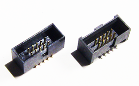
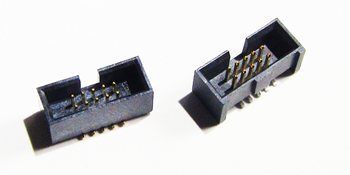

You can clearly see the undercut on the Samtec part on the
right. You can also see that the sides of the part extend down
further than the body, enabling it to sit on the plastic and not
just on the pin headers. This second feature is nice, but probably
overkill for most modules. IOW, it's quality, but I'm not sure it's
worth the price premium. The extra bump/key on the outside is
helpful for positioning during assembly, but doesn't serve any
mechanical purpose on an assembled Gadgeteer or Netduino GO board.
All you need is the notch. Note that every commercial module and
main board I've bought all use the more generic chinese parts.
The undercut is helpful, though. Just look at how much more of
the pin it exposes to your iron.
So, if you are new to soldering, I recommend using the more
expensive Samtec part. If you have a reasonable amount of soldering
experience and/or can make the pad a little longer than the stock
footprint (see next section), you can get the inexpensive
sockets.
Techniques for designing and soldering the connector
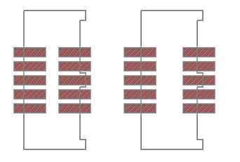
For your own modules, I recommend making the size of the pads a
bit longer than the specifications. This will take up a tiny bit
more room on the board, but make it easier for you to get your
iron. Below are the two profiles: default on left, my current one
on the right. Note that I intend to adjust the hand-solder one a
bit to make the pads longer so they come into the center a bit
better. As they are right now, you can't get a fillet
on the heel of the pins. That's hard to do anyway, but I want as
strong a connection as possible.
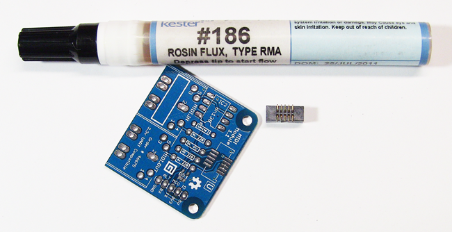
When hand-soldering, first apply flux to all the pads. You may
also want to apply flux to the pin bases on the socket -- it
certainly won't hurt, especially if the pins look a little
dirty/oxidized.
Step 1: Tin one pad
I recommend then tinning one pad in the corner with a little
solder. You don't want a giant blob here. As long as you get the
whole pad tinned, less is better.
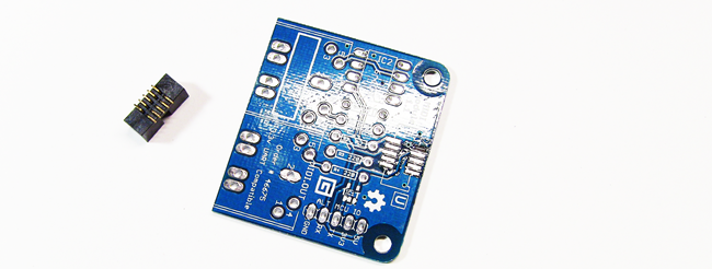
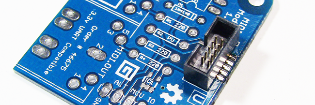
Step 2: Install the socket
Then, holding the socket in place with your fingers (by the
plastic), melt the solder to wet the one pin and hold the socket in
place while applying downward pressure to make sure it seats flat.
I used to tin all the pads, but I've found it much easier to tin a
single pad. You're not looking to make an electrically
sound connection here, just something to hold the socket
flat.
If you need to adjust the position of the socket, make
sure you completely melt the solder on that pad. If it's
only half-melted, the leverage you have with the socket will rip up
the pad. I did this once. Not good!
Look at the board edge-on and make sure the connector is seated
flat and the pin is touching the pad, not suspended above it on a
blob of solder.
Step 3: Secure the socket at the opposite corner
Then, once the socket is in the correct position and all pins
are centered on the pads (or close) and sitting completely flat,
solder the opposite pin to firmly hold the connector in place.
Don't apply too much pressure, or you'll move the socket and
possibly tear up the first pad you soldered. Once you get past this
part, all the tricky parts are done.

Step 4: Solder the remaining pins (including the first
one)
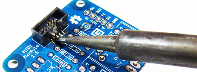
Then, solder each pin, including the first one you tinned. The
pins are a bit chunky for drag
soldering, so you really need to do one pin at a time.
I do this by using a relatively fine chisel tip on my iron. I
touch the side of the pin along with the pad at the same time and
then add enough solder to ensure a strong connection. Make sure you
heat both the pad and the pin. You can see here how the larger pads
really help with hand-soldering. If you have a larger tip, you will
end up heating more than one pin at a time, but it will be more
difficult to get the pads. In that case, apply a bit of downward
pressure to try and transfer heat between the pin and the pad.
The sockets are pretty robust, but try not to touch the plastic
with the iron. It's normal for flux to smoke a little, but you
don't want that extra special kind of smoke that comes from burning
plastic.
Step 5: Inspect and Check
I tend to use a little too much solder on these joints. You can
use a bit less than what I have here. Getting a nice fillet with
these sockets is hard, though. Even the commercial modules and main
boards tend to have a bit too much solder here, so I wouldn't worry
too much about it as long as the connection is sound and the solder
isn't adhering to the plastic.


That's it! Visually inspect the board from a number of angles to
make sure everything is soldered correctly and that there are no
bridges. Using a multimeter, you can check each pin against some
other connected part of the board to ensure continuity.
