At several recent events (VSLive Redmond, thatConference, the
Heartland Developer Conference and more), I've had a neat little
.NET Micro Framework robot with me. The remote control for the
robot is a Windows 8 tablet running a simple Modern UI/Windows
Store app I wrote in C#/XAML. The example shows both how you can
use C# skills to build robots, and also how flexible the new
Windows Store app model is when it comes to communicating with
remote devices.
Video
When on campus, I also recorded a video with Robert Green. You
can see it here:
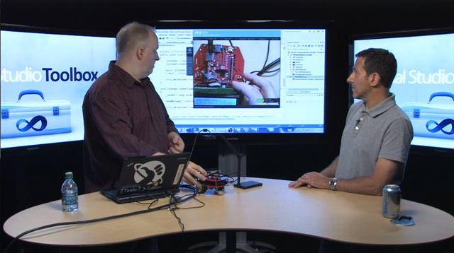
http://channel9.msdn.com/Shows/Visual-Studio-Toolbox/Windows-8-and-the-NET-Micro-Framework
The remainder of this post will explain what you need to do to
build one yourself.
Parts
Although they're out there, it's rare to find a robot as a
complete kit. Typically you need to assemble one from a number of
different parts. Here are the parts I used.
The body
When you create a robot, it can be a huge help to start with a
chassis kit.
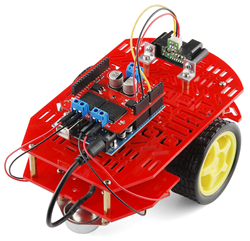
Sparkfun
Magician Chassis $14.95
The chassis comes with two motors, the robot body, assembly
screws and stand-offs, two wheels, one ball coaster, and 4xAA
battery holder. The motors are cheap, and unbalanced, but … they're
cheap! This is a great chassis for experimentation and includes a
set of features almost unheard of at this price point. To get
anything significantly better, you start looking at hundreds of
dollars including specialized battery packs and more.
The photo shows an Arduino-based solution; the kit doesn't come
with any electronics.
The brain
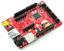
The the brain, I used the FEZ Cerbuino Bee. $39.95 at
GHI Electronics. This is an interesting little Gadgeteer
mainboard which also has Arduino-compatible pin headers and,
importantly for this robot, an XBee socket as well as normal
Gadgeteer sockets.
Wireless
The robot and PC need some way to communicate with each other.
The easiest and most reliable is to use TCP streaming sockets
across a wireless network.
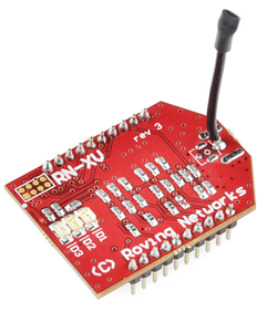
Roving networks RN-XV WiFly Module with wire antenna. $34.95 at
Sparkfun . You could also go with a regular Gadgeteer Wireless
module, but those more than twice as much and require the FEZ
Spider for the main board. That said, the NETMF driver for the full
Gadgeteer board is likely more fully featured.
This is a nice and inexpensive module. You can get other WiFi
modules, many with even better drivers. I found this one to be
adequate for this project.
Motor controller
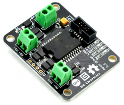
You never power motors directly from the pins on a
microcontroller. Instead, you use a specialized motor driver board
which has a second power supply input, dedicated to powering the
motors. For this, I used the Motor Driver L298 Module $29.95 at
GHI Electronics.com . That module can control two motors.
Motor power
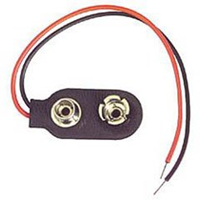
9v battery connection. Radio Shack or other retailers. It's just
a 9v battery connector with two wires hanging from it, like these ones from Amazon.
You can also get them for dirt cheap from places like Tayda Electronics. That's probably where mine
originated. It's not worth ordering through them just for this,
however.
Optional LCD Character display
I used a 4 line by 20 character LCD module I had hanging around.
To interface that with the Gadgeteer, I used the HD44780 module ($4.95 at GHI Electronics) which
I soldered directly to the board. They also sell a module which includes a two line LCD already
soldered. When purchasing your own LCD, just get one which is
compatible with the HD44780 controller. For example.
Optional sensor
I wanted something for the robot to sense. I happened to have
one of the Gadgeteer temperature/humidity sensors hanging
around. This is not a required part of the project, but just a fun
little addition.
Wireless Hub / Router
You need to connect the robot and PC to something. I have a
dedicated wireless router for this, but you could use one in your
house, or anywhere else. Just keep in mind that NETMF doesn't
handle high amounts of traffic well, so you probably wouldn't want
to connect it to, say, the shared router at a conference. That
said, I haven't tried the dedicated WiFly module in those types of
scenarios, so feel free to test it out.
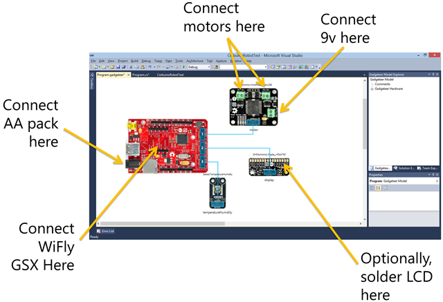
Robot Connections
Assemble the chassis. I did the chassis assembly with my two
kids; it's pretty easy, although some parts do get a little fiddly
(the motor mounts in-particular). Leave the top off for now so you
can get to the bottom deck.
Then, connect both motors to the positive and negative motor
connections on the motor module. I kept the motor module on the
bottom deck to make that easier. Because I didn't reverse the wires
on the two motor connections, but the motors are on opposite sides,
they have to be reversed in code. Positive voltage in one goes
forward, while on the other goes backwards.
Attach the 9v battery connector (without battery) to the motor
modules power input. Then, screw the whole thing down on the bottom
deck. Make sure you also secure the 9v battery wires with a washer
and screw, or even some hot glue, as you don't want the wires
pulling out of the module like they did with me at VSLive in
Redmond.
Robot Code
Now, let's get to the code.
The onboard robot code is a .net Gadgeteer project, created in
Visual Studio 2010. NETMF doesn't currently support Visual Studio
2012, but you can install VS2010 side by side with VS2012.
First, I used the WiFly module source code from Stefan Thoolen's
great .NET Micro Framework Toolbox project on
CodePlex. This project currently doesn't have support for being a
socket server, only a client. For that reason, I had to make the
Windows 8 app the server. The downside to this is the IP address
for the Windows 8 device is hard-coded into the robot, which is
opposite of what you would normally do.
The code is simple, all contained in the Program.cs file.
Explanation after the listing.
public partial class Program

{

    // This method is run when the mainboard is powered up or reset.

    void ProgramStarted()

    {

        Debug.Print("Program Started");


        InitializeMotors();

        InitializeDisplay();


        Thread t = new Thread(new ThreadStart(() =>

            {

                StartCommunications();

            }));


        t.Start();


        temperatureHumidity.MeasurementComplete += new TemperatureHumidity.MeasurementCompleteEventHandler(temperatureHumidity_MeasurementComplete);


        // report temperature on screen

        _sensorTimer.Tick += (timer) =>

            {

                _sensorTimer.Stop();

                temperatureHumidity.RequestMeasurement();

            };


        _sensorTimer.Start();

    }


    GT.Timer _sensorTimer = new GT.Timer(5000);


    void temperatureHumidity_MeasurementComplete(TemperatureHumidity sender, double temperature, double relativeHumidity)

    {

        DisplayStatus(2, "Air temp: " + System.Math.Round(temperature).ToString() + "c/" + System.Math.Round((9.0 / 5.0) * temperature + 32) + "F");

        _sensorTimer.Start();

    }


    private void InitializeDisplay()

    {

        display.Clear();

        display.TurnBacklightOn();

    }


    private void DisplayStatus(byte row, string status)

    {

        if (status.Length < 20)

            status += new string(' ', 20 - status.Length);

        else

            status = status.Substring(status.Length - 20, 20);


        display.SetCursor(row, 0);

        display.PrintString(status);


    }


    private void InitializeMotors()

    {

        motor.MoveMotor(MotorControllerL298.Motor.Motor1, 0);

        motor.MoveMotor(MotorControllerL298.Motor.Motor2, 0);

    }


    private WiFlyGSX _wifi = new WiFlyGSX();


    private void StartCommunications()

    {

        _wifi.DebugMode = true;


        DisplayStatus(0, "Initializing WiFi");


        _wifi.EnableStaticIP("192.168.1.3", "255.255.255.0", "192.168.1.1", "192.168.1.1");


        _wifi.JoinNetwork("Apshai", 0, WiFlyGSX.AuthMode.WPA2_PSK, "noisyhat801");


        bool noIP = true;

        while (noIP)

        {

            noIP = _wifi.LocalIP == "0.0.0.0";

            System.Threading.Thread.Sleep(250);

        }


        Debug.Print("WiFly IP  :" + _wifi.LocalIP);

        Debug.Print("WiFly MAC :" + _wifi.MacAddress);

        DisplayStatus(0, "IP: " + _wifi.LocalIP);


        EnableSockets();


    }


    SimpleSocket _socket;

    private void EnableSockets()

    {

        Debug.Print("Creating socket");


        string name = "192.168.1.2";

        ushort port = 5150;


        DisplayStatus(1, ">>" + name + ":" + port);

        _socket = new WiFlySocket(name, port, _wifi);


        Debug.Print("Connecting");


        try

        {

            _socket.Connect();

        }

        catch (Exception ex)

        {

            Debug.Print("Connection failed: ");

            Debug.Print(ex.ToString());

            DisplayStatus(2, "Connection failed");

        }


        var t = new Thread(new ThreadStart(() =>

            {

                while (true)

                {

                    var cmd = _socket.Receive();


                    if (cmd.Length != 0)

                        ProcessCommand(cmd);


                }

            }));


        t.Start();

    }


    private void ProcessCommand(string command)

    {

        DisplayStatus(3, command);


        // remember, motors are opposite of each other


        //one motor runs faster than the other so it's always moving an an arc

        const double motor1Factor = 1.0;

        const double motor2Factor = 0.5;


        switch (command)

        {

            case "/robot/panic":

                motor.MoveMotor(MotorControllerL298.Motor.Motor1, (int)(0 * motor1Factor));

                motor.MoveMotor(MotorControllerL298.Motor.Motor2, (int)(0 * motor2Factor));

                break;

            case "/robot/move/forward":

                motor.MoveMotor(MotorControllerL298.Motor.Motor1, (int)(100 * motor1Factor));

                motor.MoveMotor(MotorControllerL298.Motor.Motor2, (int)(-100 * motor2Factor));

                break;

            case "/robot/move/backward":

                motor.MoveMotor(MotorControllerL298.Motor.Motor1, (int)(-100 * motor1Factor));

                motor.MoveMotor(MotorControllerL298.Motor.Motor2, (int)(100 * motor2Factor));

                break;

            case "/robot/move/stop":

                motor.MoveMotor(MotorControllerL298.Motor.Motor1, (int)(0 * motor1Factor));

                motor.MoveMotor(MotorControllerL298.Motor.Motor2, (int)(0 * motor2Factor));

                break;

            case "/robot/turn/left":

                motor.MoveMotor(MotorControllerL298.Motor.Motor1, (int)(100 * motor1Factor));

                motor.MoveMotor(MotorControllerL298.Motor.Motor2, (int)(100 * motor2Factor));

                break;

            case "/robot/turn/right":

                motor.MoveMotor(MotorControllerL298.Motor.Motor1, (int)(-100 * motor1Factor));

                motor.MoveMotor(MotorControllerL298.Motor.Motor2, (int)(-100 * motor2Factor));

                break;

            case "/robot/turn/stop":

                motor.MoveMotor(MotorControllerL298.Motor.Motor1, (int)(0 * motor1Factor));

                motor.MoveMotor(MotorControllerL298.Motor.Motor2, (int)(0 * motor2Factor));

                break;

        }

    }

}
The program starts by initializing the motors and the display.
Initializing the motors to 0 simply ensures they are turned off.
The display is initialized with a simple message. Then, I start a
background thread which kicks off the communications. It's a
background thread because inside that code, I need to loop until
the device gets an IP address. Even when using a static IP, this
can take a second. With DHCP it's even more important.
Once the device gets an IP, the code opens the socket and tries
to connect to the PC. It connects to 192.168.1.2, port 5150. If
your Windows PC ends up on a different IP, you'll need to change
this.
Once the socket is open, the code kicks off yet another
background thread which simply waits for data to come in on the
socket and the processes that data by calling ProcessCommand.
ProcessCommand handles all the actual translation of movement and
display. See those calls to MoveMotor? See the 100 and -100 values?
Those are what you need to swap around if your motors are wired
differently from mine. In addition, you'll need to tweak the
motor1Factor and motor2Factor values to suit the balance of the
motors, tire friction etc, on your robot. Basically see which way
it's turning when you want it to go straight, and then multiply the
opposite motor by something less than 1. For example, if it's
turning right, multiple the left motor by 0.7 or something.
Next up, the controller app.
Windows 8 App
When I first saw the networking support available to Windows 8
apps, I was pretty psyched. I did a lot of networking work in
Silverlight, including some sockets (shudder). What we have in
Windows 8 is not only a lot simpler, but it also does not have the
port and protocol restrictions Silverlight has because WinRT apps
weren't designed to be run in a web browser on the public
Internet.
Here's the UI. It's very simple: just four boxes sized and
positioned for touch.
XAML
<Page

    x:Class="WindowsRobotController.MainPage"

    IsTabStop="false"

    xmlns="http://schemas.microsoft.com/winfx/2006/xaml/presentation"

    xmlns:x="http://schemas.microsoft.com/winfx/2006/xaml"

    xmlns:local="using:WindowsRobotController"

    xmlns:d="http://schemas.microsoft.com/expression/blend/2008"

    xmlns:mc="http://schemas.openxmlformats.org/markup-compatibility/2006"

    mc:Ignorable="d">


    <Grid Background="{StaticResource ApplicationPageBackgroundThemeBrush}">

        <Rectangle x:Name="TurnLeftTouchPoint" Fill="#FFF4F4F5" HorizontalAlignment="Left"

                   Height="143" Margin="10,447.76,0,0" Stroke="Black"

                   VerticalAlignment="Top" Width="255"

                   PointerPressed="TurnLeftTouchPoint_PointerPressed_1"

                   PointerReleased="TurnLeftTouchPoint_PointerReleased_1"/>


        <Rectangle x:Name="TurnRightTouchPoint" Fill="#FFF4F4F5"

                   HorizontalAlignment="Right"

                   Height="143" Margin="0,448,10,0" Stroke="Black"

                   VerticalAlignment="Top" Width="255"

                   PointerPressed="TurnRightTouchPoint_PointerPressed_1"

                   PointerReleased="TurnRightTouchPoint_PointerReleased_1"/>


        <Rectangle x:Name="GoBackwardsTouchPoint" Fill="#FFF4F4F5"

                   HorizontalAlignment="Center"

                   Height="143" Margin="0,0,0,177" Stroke="Black" Width="255"

                   PointerPressed="GoBackwardsTouchPoint_PointerPressed_1"

                   PointerReleased="GoBackwardsTouchPoint_PointerReleased_1" VerticalAlignment="Bottom"/>


        <Rectangle x:Name="GoForwardsTouchPoint" Fill="#FFF4F4F5"

                   HorizontalAlignment="Center"

                   Height="143" Margin="0,0,0,371" Stroke="Black" VerticalAlignment="Bottom" Width="255"

                   PointerPressed="GoForwardsTouchPoint_PointerPressed_1"

                   PointerReleased="GoForwardsTouchPoint_PointerReleased_1"/>


    </Grid>

</Page>
Note that I used Rectangle elements instead of buttons. This is
because I wanted to track separate up and down events, not a single
click event. That will become more obvious once you look at the
code-behind.
Code-Behind
Keeping things simple here: no commands or viewmodels, just a
chunk of code-behind.
using System;

using Windows.UI.Xaml.Controls;

using Windows.UI.Xaml.Input;

using Windows.UI.Xaml.Navigation;


// The Blank Page item template is documented at http://go.microsoft.com/fwlink/?LinkId=234238


namespace WindowsRobotController

{

    public sealed partial class MainPage : Page

    {

        public MainPage()

        {

            this.InitializeComponent();


            RobotService.Current.Listen();

        }


        /// <summary>

        /// Invoked when this page is about to be displayed in a Frame.

        /// </summary>

        /// <param name="e">Event data that describes how this page was reached.  The Parameter

        /// property is typically used to configure the page.</param>

        protected override void OnNavigatedTo(NavigationEventArgs e)

        {

        }


        private void TurnLeftTouchPoint_PointerPressed_1(object sender, PointerRoutedEventArgs e)

        {

            RobotService.Current.StartTurningLeft();

        }


        private void TurnLeftTouchPoint_PointerReleased_1(object sender, PointerRoutedEventArgs e)

        {

            RobotService.Current.StopTurning();

        }


        private void TurnRightTouchPoint_PointerPressed_1(object sender, PointerRoutedEventArgs e)

        {

            RobotService.Current.StartTurningRight();

        }


        private void TurnRightTouchPoint_PointerReleased_1(object sender, PointerRoutedEventArgs e)

        {

            RobotService.Current.StopTurning();

        }


        private void GoBackwardsTouchPoint_PointerPressed_1(object sender, PointerRoutedEventArgs e)

        {

            RobotService.Current.StartMovingBackward();

        }


        private void GoBackwardsTouchPoint_PointerReleased_1(object sender, PointerRoutedEventArgs e)

        {

            RobotService.Current.StopMoving();

        }


        private void GoForwardsTouchPoint_PointerPressed_1(object sender, PointerRoutedEventArgs e)

        {

            RobotService.Current.StartMovingForward();

        }


        private void GoForwardsTouchPoint_PointerReleased_1(object sender, PointerRoutedEventArgs e)

        {

            RobotService.Current.StopMoving();

        }

    }

}
The events simply call methods on the RobotService
RobotService class
This is where the magic happens. The RobotService is the socket
server and communication hub for the Windows 8 app.
using System;

using System.Collections.Generic;

using System.Diagnostics;

using System.Linq;

using System.Text;

using System.Threading.Tasks;

using Windows.Networking;

using Windows.Networking.Sockets;

using Windows.Storage.Streams;


namespace WindowsRobotController

{

    class RobotService

    {

        private static RobotService _current;

        public static RobotService Current

        {

            get

            {

                if (_current == null)

                    _current = new RobotService();


                return _current;

            }

        }


        public void PanicStop()

        {

            // this is not as cool or as scary as it sounds

            SendMessage("/robot/panic");

        }


        public void StartMovingForward()

        {

            SendMessage("/robot/move/forward");

        }


        public void StartMovingBackward()

        {

            SendMessage("/robot/move/backward");

        }


        public void StopMoving()

        {

            SendMessage("/robot/move/stop");

        }


        public void StartTurningLeft()

        {

            SendMessage("/robot/turn/left");

        }


        public void StartTurningRight()

        {

            SendMessage("/robot/turn/right");

        }


        public void StopTurning()

        {

            SendMessage("/robot/turn/stop");

        }


        private StreamSocket _socket;


        public bool IsConnected { get; set; }


        private RobotService()

        {

            IsConnected = false;

        }


        private StreamSocketListener _listener;

        public async void Listen()

        {

            _listener = new StreamSocketListener();

            _listener.ConnectionReceived += listener_ConnectionReceived;


            await _listener.BindServiceNameAsync("5150");


            Debug.WriteLine("Listening on port " + _listener.Information.LocalPort);

        }


        void listener_ConnectionReceived(StreamSocketListener sender, StreamSocketListenerConnectionReceivedEventArgs args)

        {

            _socket = args.Socket;


            SendMessage("/robot/welcome");


            Debug.WriteLine("Connection received: " + _socket.Information.LocalAddress.RawName + ":" + _socket.Information.LocalPort);

        }


        // we're talking to only one client, so need only one writer

        // keep a dictionary identified by endpoint if you need multiple

        DataWriter _writer = null;

        private async void SendMessage(string message)

        {

            if (_writer == null)

            {

                var stream = _socket.OutputStream;

                _writer = new DataWriter(stream);

            }


            _writer.WriteString(message);


            await _writer.StoreAsync();


        }

    }

}
The public methods send string messages (using an OSC-like URL
syntax) to the robot. They do this through the SendMessage
function. If you've ever done any socket programming in
Silverlight, you can see just how much simpler this is.
The Listen method is especially interesting. This enables the
app to be a socket server. Yep, your Windows 8 app can be a server
- as long as you set the appropriate permissions. Because I'm using
192.168 local subnet addresses, and am a server, I requested both
Internet Client/Server as well as the local networking permissions
in the appxmanifest.
What's Next?
I have already experimented with using this model to control
synthesizers and other external gear. The networking support
available for Windows 8 apps (TCP Streaming, UDP Sockets, Web
Sockets, and more) is really good for this type of use.
The Windows 8 source code and project is attached. I don't have
a downloadable project for the NETMF project yet, because the
project got a bit borked. The source above is the sum of the
source, however, so you should be able to recreate that part quite
easily.