Welcome to Pete Brown's 10rem.net

First time here? If you are a developer or are interested in Microsoft tools and technology, please consider subscribing to the latest posts.

You may also be interested in my blog archives, the articles section, or some of my lab projects such as the C64 emulator written in Silverlight.

(hide this)

Netduino Basics: Using Pulse Width Modulation (PWM)

Pete Brown - 27 September 2010

Pulse Width Modulation (PWM) is the process of alternating a signal between two extreme values with little to no intermediate steps. On the Netduino, these values are 0v and 3.3v. In its most basic form, the output resembles a square wave, where both the min and max values have the same duration.

image

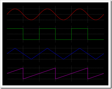
The square wave (which can be created with PWM) is the second down. The others, from the top are: sine wave, triangle wave and sawtooth wave. The place I always ran into these was in synthesizer work. For example, I supported all four waveforms in my Silverlight Synthesizer project.

For some of you, this may seem insanely simple, but for those of us just starting out in electronics, this is quite an adventure :)

PWM is used to control a number of things from servo motors (PWM is used in my CNC setup) to the level of output in LEDs to, what I intend to use it for shortly, serving as a clock signal for another chip. In my case, the chip will be a MOS 8580 SID chip salvaged from an old Commodore 64c. That'll be detailed in a later post once I get things working.

PWM on the Netduino

Four of the output ports (Digital pins 5, 6, 9 and 10) on the Netduino may be used for PWM signals. I'm using a new Netduino Plus beta, but the tech specs in this area are identical. PWM in the current firmware release is somewhat limited, but from reading Chris's posts on the forums the 4.1.1 revision of the firmware should have some real advancements in these areas.

Currently, the standard PWM clock is set to 10Khz. If you set the duty cycle, it will be based on that clock. One of the expected upcoming changes will be to have finer control over the clock, and hopefully support Mhz clock and PWM rates.

Using PWM is pretty simple. Instead of creating an OutputPort, you'll create an instance of the PWM class. Once you do that, you can either set the Duty Cycle or call SetPulse.

In this case, we'll call SetPulse and have the pulse on 1/3 of the time (basically a 33% duty cycle)

public class Program
{
    public static void Main()
    {
        PWM pwm = new PWM(Pins.GPIO_PIN_D5);

        const uint period = 3 * 1000 * 1000;    // 3 ms
        const uint duration = 1 * 1000 * 1000;  // 1 ms

        pwm.SetPulse(period, duration);

    }
}

Doing that, creates the following waveform:

image

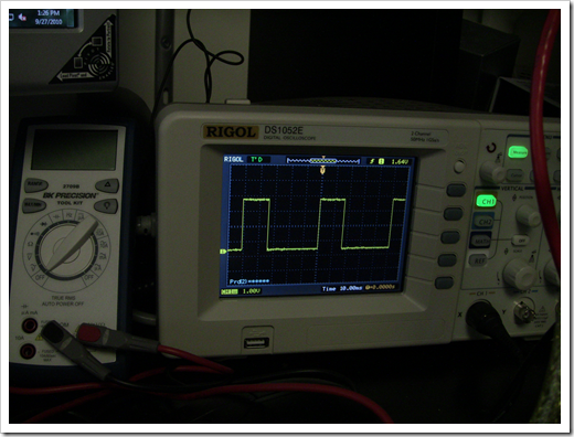
(the scope lets me save the image to a USB key, but I just unboxed it today. Photo snapshots will need to suffice for now)

The first parameter of SetPulse is the period, the second is the duration. Some definitions:

Duty Cycle Proportion of "on" time vs. the period. Expressed as a percent with 100% being fully on. This is used only with SetDutyCycle and the default clock rate.
Period "Peak to Peak" time. This is in microseconds (1/1,000,000 second). Used in SetPulse.
Duration Duration of the "on" time for a cycle. This is also in microseconds. This needs to be less than the Period. Used in SetPulse.

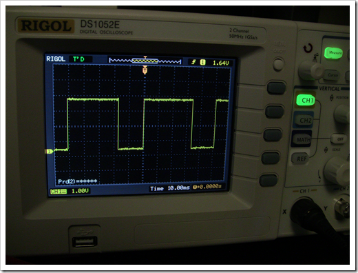
If you want to have the opposite effect; that is, a pulse that is on 2/3 of the time, the code would look like this:

public class Program
{
    public static void Main()
    {
        PWM pwm = new PWM(Pins.GPIO_PIN_D5);

        const uint period = 3 * 1000 * 1000;    // 3 ms
        const uint duration = 2 * 1000 * 1000;  // 2 ms

        pwm.SetPulse(period, duration);

    }
}

The resulting waveform looks like this. Notice how it is now "on" for 2/3 of the time:

image

Uses for PWM

In its current form, you can use PWM on the Netduino to control servos (not directly, you'll want to use it to trigger something with more volts/amps) and control the brightness of LEDs. You can also use it as a clock signal for relatively slow clocks. When the new firmware comes out, I hope to use PWM to clock the MOS 8580 SID chip I have sitting in a breadboard on my desk.

About the Netduino

The Netduino is a 100% open source hardware and software platform, pin compatible with the Arduino. It runs the .NET Micro Framework; you write code using Visual Studio 2010. For more information, see the official Netduino site.

(source code for this example is included below)


Source Code and Related Media

Download /media/67980/testpwm.zip
posted by Pete Brown on Monday, September 27, 2010
filed under:            

20 comments for “Netduino Basics: Using Pulse Width Modulation (PWM)”

  1. Tomsays:
    That is really cool. My experience with PWM has only been using fan controllers on motherboards and graphics cards. It's nice to read about some other uses, although a little scary. If something went wrong with the PWM, could your 8580 be hurt? If it was a motor or something easily replaceable that would be no big deal, but the loss of an actual SID chip would be unfortunate.
  2. Petesays:
    @dezen

    The scope was $399. I've always been fascinated with oscilloscopes, but haven't been able to afford one. I also don't have the knowledge to effectively pick and tune a used one.

    We all have our vices. Mine is gadgetry :)

    Pete
  3. Snympisays:
    Nicely done Pete. I've ordered my Netduino today. Hope you and Scott keep the rivalry going because we keep getting better and better examples.

    I think buying a nice scope saves a lot of trouble in the long run. You can start with something cheap and dirty and after the 10th upgrade end up with something nice, or you could just get a nice one first time around.
  4. Paul Newtonsays:
    Hello Pete,

    I have just started to play with a netduino plus and wish I had had one twenty years ago!
    I have found web pages like yours great for getting going - thanks for sharing the knowledge.

    I tried out an LED dimmer based on your code above and got some strange results with the LED brightness jumping up and down as I swept the duty cycle using SetPulse in a loop.

    I think there is a mistake in the code snippet you included:
    const uint period = 3 * 1000 * 1000; // 3 ms
    const uint duration = 2 * 1000 * 1000; // 2 ms
    your words prior to the code say the period and duration are in microseconds, but that makes the values above 3 and 2 seconds not 3 and 2 milliseconds.

    I do not have access to a scope at home to check the period I ended up with (I was aiming for 20ms e.g. 50Hz). I think the following is a 50% duty cycle at 20ms:
    const uint period = 20 * 1000; // 20 ms
    const uint duration = 10 * 1000; // 10 ms

    Perhaps you have mixed in some of the MHz timing you mention earlier?

    Thanks - Paul
  5. Igorsays:
    Hello,

    I would like to know where did you get the information abot PWM clock beeing set to 10khz by default. I don´t have an osciloscope to check it out nor very familiar with this microcontroller.

    In adition, I tought the "SetPulse" method would trigger a single pulse (my bad). However, I noticed that you did not included an infinite loop (while(true)) at the end of the main method nor a infinite timeout.

    Thank you,

    Igor.
  6. Andysays:
    Thanks for the great info, Pete. I notice you're using the Rigol DS1052E, also recommended by Dave on EEVBlog. Considering getting one myself as a New Years gift (any excuse will do!) Interested in your experience, feedback & recommendations regarding it. Thanks!

    --Andy
  7. Petesays:
    @Andy

    Thanks.

    The Rigol: I love it. Note that you can get the 100MHz DS1102E version at just about the same price now. hit http://www.saelig.com/PSBE100/PSPC017.htm . If the prices were this close when I got my 50MHz version, I would absolutely have picked up the 100MHz version instead. Both are still great scopes, though.

    Pete
  8. Petesays:
    @Igor

    I believe I got that on the Netduino forums.

    Actually, I see you got clarification that it is indeed 10KHz in .NETMF 4.1

    http://forums.netduino.com/index.php?/topic/3097-pwm-clock/page__p__21627__hl__10khz__fromsearch__1#entry21627

    Pete
  9. JeffreyJsays:
    Pete,

    I just my Netduino and the first project I want to do is a PID temperature controller for making beer. I think your PWM code will do the heater control duty. Thanks for the conrib. I'll post my results.
  10. Petesays:
    @JeffreyJ

    I don't have any PWM code other than what I showed here. I definitely don't have a proper PID implementation.

    Have you asked on the Netduino forums http://netduino.com ? I bet someone will have a built module for you.

    Pete
  11. Steve Andrewssays:
    Pete, your code shows a single parameter for the PWM constructor, but I get an error saying it takes more parameters - four or five depending on the overload. Why am I seeing this differently? What do these additional parameters do?
  12. Frodesays:
    Note that the PWM class used in this example is from the SecretLabs.NETMF.Hardware.PWM.dll assembly. It has been been made obsolete by a PWM class in the .NET Micro Framework 4.2 which has a different signature.

Comment on this Post

Remember me