Not too long ago, I got my hands on a Netduino (an
Arduino-compatible board you program using the .NET Micro Framework
and Visual Studio 2010), and did the
obligatory BlinkenLight application. Afterwards, Scott way
one-upped me and
built an awesome morse code app. The stakes were getting
higher, so I had to do something that seemed cooler than morse
code. Hard to top, I know. I bet Hello World would do it! ;)
So, I purchased an LCD through Hacktronics,
via Amazon. The LCD is no longer listed as available, but
Hacktronics has other LCDs
you can order through their site. The LCD comes with a set of
pin headers as well as a resistor for the backlight LED. You need
to solder the headers on yourself. The board is covered in solder
resist, so this isn't actually very difficult.
To use this LCD, which is controlled by a HD44780 LCD
Controller, you'll need to either roll your own LCD library, or use this awesome
library on codeplex. You can imagine which one I prefer. There
are no official releases for that library, so you'll want to just
download the source and add it to your project.
The CodePlex project provides the LCD class, and the GPIO 4 and
8 bit implementations. There's also an implementation using a shift
register to cut down on pin count, but I'm not there yet.
Wiring the LCD to the Netduino
I found a number of wiring approaches online, but they differed
in significant ways (more than just data pin assignments). The one
that is closest to what I used is
this table here (I really owe these guys for this post, as that
is what finally made it gel for me). The actual pin assignments are
as follows:
| LCD Pin Number |
Symbol |
Netduino Pin |
Description |
| 1 |
VSS |
GND |
Ground |
| 2 |
VDD |
5V |
Logic voltage |
| 3 |
V0 |
10K Pot Leg 2 |
op voltage for LCD. Controls
color/contrast |
| 4 |
RS |
D12 |
Register selector |
| 5 |
R/W |
GND |
Low means write, so you can just
ground it |
| 6 |
E |
D11 |
Chip enable |
| 7 |
DB0 |
D9 |
Data Bit 0 |
| 8 |
DB1 |
D8 |
Data Bit 1 |
| 9 |
DB2 |
D7 |
Data Bit 2 |
| 10 |
DB3 |
D6 |
Data Bit 3 |
| 11 |
DB4 |
D5 |
Data Bit 4 |
| 12 |
DB5 |
D4 |
Data Bit 5 |
| 13 |
DB6 |
D3 |
Data Bit 6 |
| 14 |
DB7 |
D2 |
Data Bit 7 |
| 15 |
LED(+) |
Resistor to 5V |
Backlight LED Anode |
| 16 |
LED(-) |
Ground |
Backlight LED Cathode |
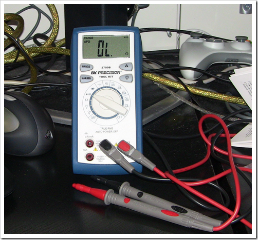
I had a hard time with some initial wiring diagrams (ones that
completely left out the backlight ??). I initially suspected my
soldering, but luckily I have a brand spanking new BK Precision
2709B with a continuity meter.
I checked each of the solder pads against the pins and found
they were all fine. In the end, it was just that the backlight was
left out of other
diagrams, or
wired to a pin that isn't inherently supported by the Netduino LCD
library (presumably I could have just set that pin high to turn
on the backlight. I'll try that later). Here's the whole wiring
mess:
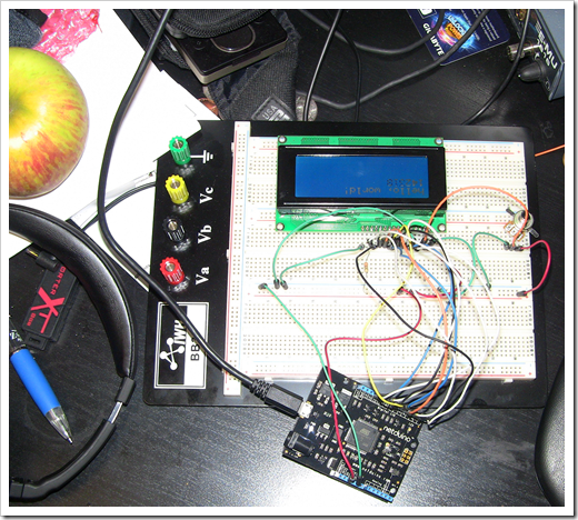
Look, I even have an Apple on my desk ;) Seriously, the wiring
is a mess. I found myself wishing I had more than just a few colors
of jumper wires. Nevertheless, it works. (Yes, it's upside down
because my USB cable is very short and stiff. I need to get a
better micro USB cable)
Testing with Hello World
I tried to use the sample applications included in the codeplex
project, but I got a really obscure error with the debugger, and
was unable to deploy. It may have to do with mismatched versions of
something, but I didn't have time tonight to dig in deeper.
So, what we'll do is copy the relevant code to our own new
Netduino project. Once I did that, and modified the LCD constructor
call to reflect the pins I used, all was good. Here's the code:
public static void Main()
{
    var lcdProvider = new GpioLcdTransferProvider(
        Pins.GPIO_PIN_D12,  // RS
        Pins.GPIO_NONE,     // RW
        Pins.GPIO_PIN_D11,  // enable
        Pins.GPIO_PIN_D9,   // d0
        Pins.GPIO_PIN_D8,   // d1
        Pins.GPIO_PIN_D7,   // d2
        Pins.GPIO_PIN_D6,   // d3
        Pins.GPIO_PIN_D5,   // d4
        Pins.GPIO_PIN_D4,   // d5
        Pins.GPIO_PIN_D3,   // d6
        Pins.GPIO_PIN_D2);  // d7

    // create the LCD interface
    var lcd = new Lcd(lcdProvider);

    // set up the number of columns and rows:
    lcd.Begin(16, 4);

    // Print a message to the LCD.
    lcd.Write("hello, world!");

    while (true)
    {
        // set the cursor to column 0, line 1
        lcd.SetCursorPosition(0, 1);

        // print the number of seconds since reset:
        lcd.Write((Utility.GetMachineTime().Ticks / 10000).ToString());

        Thread.Sleep(100);
    }
}
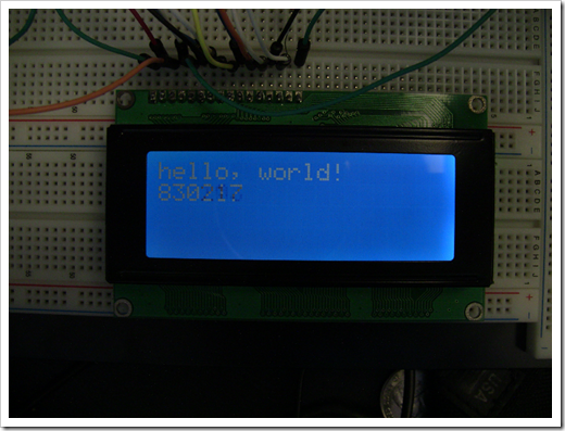
The example here prints "hello world!" on the first line, and
the machine tick count on the second line, updated every 100ms
(1/10 of a second). Here's a photo of the LCD running:
You can adjust the text color slightly by using the 10k pot.
However, it has a very limited range.
You can find information on the supported
character set for the HD44780 here. Apparently, you can also create your own
characters sets.
So, that's it. I can't really explain in a blog post just how
gratifying it is to write microcontroller code in .NET, and see
results in something that is not being driven by a regular old
computer. Seriously, it's super cool.
Source code is included below.