(project completed in 2001/2002)
One of the very first projects I decided to do when I bought the
house was to replace all the existing phone and cable TV wiring
with structured wiring. This was really quite a project, and
helped to familiarize me with all the little nooks and crannies of
the place.
If you are a technically-minded person (I happen to be a
software developer), or comfortable with running electrical wires,
running wiring like this through your house yourself is not very
difficult, and will save you a ton of money.
Important Note: Some time after I completed
this work, when I was investigating getting a permit for wiring my
shed for my woodworking tools, I found out that 1. It would have
required a permit and 2. Homeowners where I live are not allowed to
apply for the permit or do the work themselves. In Anne Arundel
County in Maryland, even though Home Depot and Lowes sell all the
"do it yourself" stuff locally within the county,
any and all electrical, plumbing or mechanical work must be
permitted and the permit must be pulled by a master electrician,
plumber, etc. Obviously the county is not interested in safety,
only in the lobbying efforts of the professional groups. If safety
was the concern, they'd let a homeowner (who is likely going to do
a lot of things like this themselves anyway) apply for a permit and
get the work inspected and approved. Instead, the homeowners will
do the work themselves anyway and can't get it inspected.
In this Maryland county, a homeowner cannot even legally
replace a sink trap, replace a breaker, or install a
battery-operated smoke detector themselves. Yet another
case of big money lobbying groups prevailing over common sense. In
any case, check your local codes before starting any work.
One thing that made this easier in my house, is that I own a
split-level house with a drop ceiling in the basement.
Because of that, it was really easy to run wires to the various
rooms without going through two stories of wall and ceiling.
I'm not sure how well I would have done if I had to run wiring
between, say, the first and second floor of a house with a standard
basement.
Each room in my house now has at least one wall outlet with 3
cat5e and two shielded coaxial jacks. This gives me the
ability to place televisions, cameras, phones, computers, smart
devices etc. in any room.
The computer corner of our basement has two such wall outlets
(one for each computer) and the television room has one outlet
behind the couch and a more comprehensive outlet behind the
television. The outlet behind the television is a double
outlet and includes wiring for surround sound speakers as well as
the usual.
This project took me several weekends to complete after my
initial research, material purchasing, and tool purchasing (an
aside: you spend a lot of money on tools that you'll likely never
use again. If you know someone in the business, try to borrow
the tools from them instead, or maybe try to get a used set of
tools).
I estimate that after tools and materials (not including labor,
of course), this project ran me about $1500 for my entire 2400sqft
house. (9 outlets, including one extra-capabilities outlet behind
the TV). That is significantly less than one would pay a
contractor for similar work.
Tools used
- RG45 Tool
- Punch down tool
- Basic Cat5e Cable Tester (essential!)
- Specialized wire cutters and strippers for cat5/5e cable
- Specialized wire strippers for coax
- Coax crimping tool
- Cable snake / fish tape
- Drill and various drill bits
- Stud sensor
- Coax wrench
- Dremel Tool (for cutting through drywall)
- Gloves to protect your hands from insulation
- Safety Glasses to protect your eyes from insulation and
drywall
- Paper dust mask to protect your lungs from inslation and
dust
- Baseball Cap to protect your head from insulation
In addition to all the connectors, outlets etc. you will want to
get a ton of black electrical tape, and at least as many different
colors of electrical tape as you have similar wires. For
example, I have three Cat5e cables per run, plus two coax, so three
different colors worked fine.
How I Pulled Cable at My House
Please keep in mind that I am not a professional electrician or
a cable-puller in the telecom industry. I'm just a guy who
did this in his house :-). Also keep in mind that my house
was already built and finished, and happens to be a split-level
with a drop ceiling in the basement. Typically, I had time to do
one room per day. That includes bundling the cables, cutting
the outlet hole, running the cable, and connecting up the outlet
jacks. It does not include the time taken at the end to
connect up the main wiring center or test the cable. Given
that, this is how I typically approached the install for any given
outlet :
- Plan the outlet location.To do this you need to take into
account several important things:
a) Make sure the outlet isn't near an electrical outlet, switch
or fixture. It should be a good eight inches or so away from any
electrical interference. You want to make sure there is no
electrical interference. When it comes to fluorescent lights,
it is typically worth it to run an extra x feet of cable simply to
avoid coming anywhere near the massive interference a fluorescent
light puts out.
b) Make sure you have a clean run from the wall outlet location,
through the ceiling or floor, to the central wiring location.
You want to make as few holes in floor joists as possible (and make
sure the holes are small so you don't weaken the joist).
c) Make sure the outlet is in a place close to where you expect
to use it! In my TV room, for example, I put a set of outlets
behind the television (with network outlets for things like TiVO,
online games etc.), and another set behind the end-table, as that
is where the telephone is typically located.
d) Make sure the cable run isn't going to follow close to a hot
water pipe. You don't want to melt your cable insulation.
e) Make sure there aren't any sharp bits of metal along the
planned route. This includes the bare edges of the suspended
ceiling supports. If there are sharp bits of metal, make a
note to avoid them, or grind them blunt with your Dremel
tool. It you simply tape over the sharp bits, the tape will
wear out.
- Cut the outlet hole. I found the Dremel drywall cutting
attachment on my Dremel tool to be the easiest way to handle
this. Make sure you put newspaper (taped to the baseboard
trim) on the floor to catch the drywall dust
- Insert the metal outlet mount in the wall. This is what
the outlet plate will attach to. I insert it before running
cable as it helps prevent damage to the nicely-cut outlet.
- Put a bit of colored electrical tape on each reel or box to
identify that box. Then, wrap the same color at the end of
each cable that you pull from that box or reel. It will help
if you put the color on the cable in about a foot or so from the
end. This is how you will identify which cable is which when
you get the cable to the destination.
- Wrap a good amount of electrical tape around the bundle of five
cables. Make sure they are not splayed-out at the end.
If you have a nice tight point, it will make running through the
wall much easier
- Feed out a little less bundle than you think you will need to
run from the outlet to the central wiring box/hub and tape it with
electrical tape every foot or two, neatly coiling it up on the
floor while you do so. The rig you see in the first photo
below is something I set up specifically to aid in this
operation. Taping and coiling neatly will keep the bundle
together, and help prevent snags
- Try to ensure you are setup in a way that will allow you to
pull the cable to the outlet using the fish tape. Select your
outlet location and feed areas based on this.
- Run the fish tape through the open area in the drop ceiling and
down (or up, if this is an upstairs room) to the outlet. To
avoid getting hung up on insulation, I would use pliers to crimp
the fish tape and closed, and would sometimes even use electrical
tape on it to ensure that it would not snag if backed-up. If
you can pull cable through non-insulated interior walls, you will
be that much better off. In general, I found it easiest to
run from an outlet, to the wiring hub, not the other way
around. A straightened coat hanger pushed around inside the
outlet hole can help you locate the end of the fish tape in between
the studs in the wall.
- Once you have the fish tape end sticking a couple feet out of
the outlet, you are ready to pull cable.
- Hook the end of the fish tape into the taped point on your
cable bundle. Make sure the cable is oriented in such a way
as to ensure that pulling the fish tape will pull the cable
point-first.
- Tape the bundle really really well to the fish tape. The
bundle is going to take a lot of abuse when pulled through the
wall, and you don't want to lose it! Also, make sure the tape
forms a nice taper from the fish tape to the bundle. Any
blunt end is going to get hung up either at the destination when
you try and pull it through the hole you made in the wall, or more
likely, in the insulation in the wall.
- Unless you like fiberglass splinters from your insulation, now
is when you want to put on some gloves and a breathing mask.
- Pull the fish-tape slowly. It can help here to have
someone else feed the cable into the wall. Stop pulling once
the cable end is sticking out of the wall several feet (enough to
make sure it isn't going to fall back inside the wall)
- Now is a good time to go grab a coke or something :-)
- Now you need to run the cable to the wiring location using the
route you decided upon in step 1. If you have a drop ceiling,
or an open-ceiling basement, this will help tremendously. Make sure
you secure the cable to joists with cable clips and zip-ties so
that the cable is not drooping and vulnerable to accidental
slicing. If you must cut into joists, make the cuts small -
follow the hole sizing and protection rules you can find in any
Home Depot / Lowes / Black & Decker "Do it yourself electrical
wiring" type book. While pulling the cable, make sure it does
not catch or wear on any of the holes you cut.
- Before cutting the cable from the reel, tape the colored
electrical tape around each cable in two spots : one just about 2
inches out of the wall, and one about a foot from there.
- When done, you should have a few feet of extra cable at the
wiring center, and two feet or so of extra cable at the outlet
end. You need to ensure you have a little slack, and enough
wire to strip more than once should you mess up on either end
:-)
- Start on the next outlet :-)
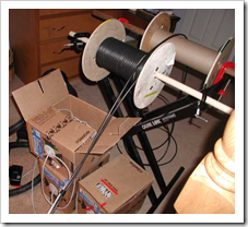
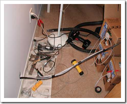
Here is a photo of the mechanism I used to make bundling wires
easier. As this photo was taken during the last jack
installation, the spools are almost empty. (Notice I have one cable
source/spool for each wire in my bundle. It is far too
cumbersome to try and save money by sharing a single spool across
two cables in the bundle. Because of that, I manually ran
half of the coax I bought onto an empty spool I picked up at the
wiring store.) Basically it is just a couple dowels held down
on keyboard stand using C clamps. I bundled the cables with
electrical tape as they came off the spool. If you want to do
this yourself, and do not have specific requirements, you may be
able to use the pre-bundled cable sets.
Notice that the front RG45 reel has yellow tape, the rear has
green tape. The individual Cat5e boxes have green, red and
blue tape on them as well. This is what uniquely identifies
each cable in the run.
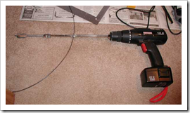
Here is a photo of the shaft extension I used to drill through
the floor in the wall in the master bedroom. The master
bedroom wall is an outside wall that overhangs the lower level by
about two feet, so it was the most difficult installation in the
house. The way I made it work is I ran the fish tape through
the outlet location (a location that was selected because it is
near the open-ceiling area in the basement hot water heater
closet), and hunted for it in the basement. Not exactly the
most efficient way, but it worked :-)
Here you see the cable bundle being fed into the wall. It
took me forever with a cable snake to figure out where downstairs
the hole came out (remember the overhang, well that makes things
just a little difficult). This one outlet followed a
different pattern than the others. Instead of fishing through
the actual outlet hole, I opened up a hole close to the floor, and
ran the wiring through there. This was simply so I could get
the correct angle to drill the hole through the floor inside the
wall. Once the cable-pulling was done, I cut a hole above
this one, added the outlet and moved the wiring up through that
outlet. I then patched the hole and Melissa repainted the
patch :-)
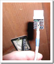
Here is the wiring for a single Cat5e jack. If I am not
mistaken, this was taken before I changed from using the A wiring
scheme to the B wiring scheme. I rewired this one set of
jacks for this one outlet, and it was good practice anyway.
Notice the colored tape on the cable that indentifies this specific
cable.
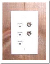
Here is a rather poor picture of one of the many jacks that now
fill all the rooms in the house. My normal convention is to
treat the top Cat 5e jack as a phone outlet, and the other two Cat
5e jacks as network outlets, but that is by no means a
requirement. Due to the layout of the wiring center in my
basement, I can change those assignments around any time I
want. To keep the cables straight, I always put the Red Cat5e
at the top, followed by the Blue and Green below. (I'm a
computer-guy, so RGB was really easy for me to remember
<g>)
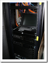
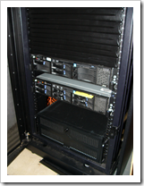
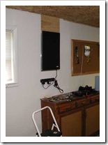
Here is the wiring panel recessed in the wall in the basement
"shop" room. The board (later painted white) above the panel
is removable to allow for access to the many wires that come into
the patch panels. For a more recent photo, select "About"
from the menu at the top.
Here is a diagram of the patch panel. My apologies for the
large image size, but the text was simply unreadable at smaller
resolutions. I never ended up getting SDSL, so the extra
(outdoor rated) cat5e cable was never used. Instead, I picked
up line-sharing DSL (ADSL). One of the nice things about this
wiring cabinet is that not only the DSL modem is located in here
now, but also all the ugly DSL line filter "dongles" that normally
would be attached to the wall on every phone in the house. In
addition, I later retired the Linksys router and purchased a
netgear ProSafe VPN router with eight 100mbit ports. The
Netgear router was far more reliable, and faster than the old
Linksys.

When I later put in the rack and upgraded to FIOS, I used a 14
port Netgear switch and the router from Verizon.