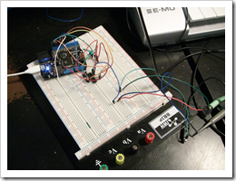
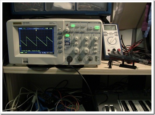
In previous two posts, I created a midi interface for the
Netduino. For kicks, here's what it looks like soldered rather than
on the breadboard (and beside it, a shot of the disaster my desk
has become during this project. There's actually a Commodore 128 in
the rubble to the right):
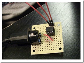
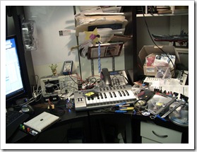
Gladly, I've since cleaned that up. :)
The two posts covering the MIDI interface are:
When tackling something new, I try and individually prototype
the key parts. I've always had a habit of doing that, especially
when I used to write business apps for a living. I'd make sure that
the prototype was throwaway, and completely divorced of any larger
solution. That really helps when you're trying to learn something
new.
The next new thing in the Netduino Synthesizer project, is to
interface to a 12 bit DAC (Digital to Analog Converter) via a
chip-to-chip protocol known as SPI.
About SPI
When you interface with a chip using parallel communications,
you typically have to have one digital I/O pin dedicated to each
I/O pin on the other chip. For 8 bit communication, you're looking
at 8 pins just for the data, plus several others for selection and
whatnot. As you can imagine, that doesn't scale particularly well,
especially when you have a very limited number of I/O pins like you
do on the basic *duino boards.
There are several chip-to-chip protocols that help you get past
that. The one we're going to use here is called SPI (Serial Peripheral Interface Bus). As the name
implies, this is a serial protocol using only a few pins for
communication regardless of the width of the message.
About the DAC
If you want to output samples of audio, you need a way to
convert digital samples to a continuous analog waveform used to
drive the speakers. One way to do that is using a DAC (Digital to
Analog Converter) Pretty much anything with audio these days has
some sort of DAC inside. I chose a relatively inexpensive 12 bit
DAC. The really good 24bit DACs run way too much for a project like
this, and almost all of the 16 and 24 bit DACs are surface mount
chips; I need DIP packages so I can have a chance of actually being
able to work with them without a microscope. There are through-hole
DIP packaged 16 bit DACs, but they all run up in the hundreds of
dollars as they aren't normal stock items at places like
Mouser.
In any case, 12 bits will give us something that is better than
8 bit, but a far cry from 16 bit CD audio. Who knows? Maybe it'll
even help lend a little character to the sound :)
The chip I selected is the MCP4922-E/P (buy, data sheet) 12 bit DIP packaged DAC. It
supports three different serial protocols (3-Wire, SPI, and
Microwire) and runs from between 2.7v to 5.5v, making it a decent
companion to the 3.3v Netduino. This DAC happens to have two
converters in the package, something I may take advantage of if I
decide to make the synthesizer output stereo samples. At $2.76 in
small quantities, the chip is a bargain.
That said, this chip isn't typically used for audio, at least
not according to the data sheet. Presumably that is because it is
only 12 bit and perhaps not as fast as some other DACs. Hopefully,
for our purposes, it will still be fine. (As it turns out, its
single DAC little brother MCP4921 is actually used on the Arduino Pocket Piano Synth Kit and the Audio Player Shield Kit, so looks like I
picked a reasonable chip)
From the 40 page data sheet for this chip, the pinout on this
DAC is as follows:
| Pin |
Function |
| 1 |
V+ (2.7v to 5.5v) A decoupling capacitor here is recommended |
| 2 |
(unused) |
| 3 |
Chip Select |
| 4 |
Serial Clock Input |
| 5 |
Serial Data Input |
| 6 |
(unused) |
| 7 |
(unused) |
| 8 |
Sync input to xfer DAC settings from
serial latches to the output latches (at the time I wrote this, I
had *no* idea what the heck that meant, but it's there to let you
keep outputs A and B in sync, as you would need in the case of
stereo output) |
| 9 |
Hardware shutdown input (to put the
DAC in stand-by mode) |
| 10 |
DAC B Output |
| 11 |
DAC B Voltage Reference. The output
will be a value from Ground to this voltage reference, divided up
into 4096 increments. |
| 12 |
Analog ground. This is your reference
base. |
| 13 |
DAC A Voltage Reference. Same as pin
11, but for DAC A. |
| 14 |
DAC A Output |
Looking at the data sheet, I had a lot of learning to do. Then
again, it would be pretty boring if this project wasn't on the
upward side of the learning curve.
According to the docs, each SPI message (that is, each sample I
send) will need to be a total of 16 bits. The bits are as
follows:
| Bit |
Description |
| 0-11 |
12 bits of sample data. Sample value
is between 0 and 4095 |
| 12 |
Output Power Down Control bit
1 = Output Power Down Control Bit
0 = Output buffer disabled, output is high impedance |
| 13 |
Output Gain Select Bit
1 = 1x (Vout = Vref * D/4096)
0 = 2x (Vout = 2 * Vref * D/4096) |
| 14 |
Vref Input Buffer Control Bit
1 = Buffered
0 = Unbuffered |
| 15 |
DAC A or DAC B Select Bit
1 = Write to DAC B
0 = Write to DAC A |
When I started with this, I got the sample info, but had no idea
what was meant by some of the things used in bits 12 through 15.
Everything used to build this project was learned in-process, so
don't be shy about trying something like this yourself. The data
sheets, while somewhat opaque at first, clear up once you start to
understand a few key concepts.
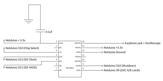
Circuit
The circuit is relatively simple. Once I figured out how to use
the various pins on the chip, the only other new concept for me was
the decoupling capacitor on pin 1. That's there to help smooth out
some of the ripple in input voltage.
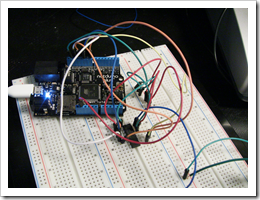
In the actual implementation, I used common ground and +3.3v
rails on the breadboard, as you can see in the above photos. Also
note that while I did hook up the Shutdown and A/B Latch pins, I
ended up not doing anything with them for this test. Shutdown will
be useful in a real scenario, when you need to put the DAC in a
low-power / sleep mode. The A/B latch will be essential for stereo
output where you need to keep the channel A and B signals in
sync.
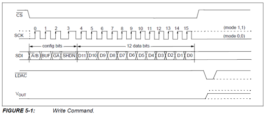
How it Works
When I output a sample, the SPI clock sends a timing signal at
the specified rate (set up when I created the SPI object). At each
clock pulse, the DAC reads a single incoming bit from the SPI
input. Since there are 16 bits to be read (12 sample and 4 control)
it takes 16 clock pulses to read a full message. This is
illustrated by figure 5-1 from the data sheet.
Prior to working with this chip, I didn't understand just how
clocks and reading bits on input pins work. Now I get it. That's
another win from playing around with this technology on this
project.
Ok, enough on the hardware background. Let's look at how to
actually generate the waveform.
Generating a Sawtooth Waveform
One of the easiest waveforms to generate is a straight sawtooth
waveform. What I actually end up generating is an inverse sawtooth
wave, where the value ramps up and slowly drops rather than the
reverse. For more information on the Sawtooth waveform, see this wikipedia
article.
For this example, I'm generating a pretty boring one, without
many interesting harmonics. If you want to create a world-class
synthesizer sound, optimizing your wave shape is essential: you
want lots of harmonics, and you want to scale nicely from one end
of the spectrum to the other.
The code that generates the waveform is encapsulated into an
oscillator class. In the world of analog synthesis (and adopted by
most digital synthesizers), oscillators are circuits that produce
the waveform which is later shaped by filters and envelopes.
The Oscillator Class
I originally generated the sawtooth waveform in real time, much
like I did with the Silverlight synthesizer. However, that was far
too slow for this device. So, I later changed it to pre-calculate a
waveform and pick samples. The wave table is a pre-calculated
representation of a single cycle of the wave form. A simplified
version of the table looks something like this:
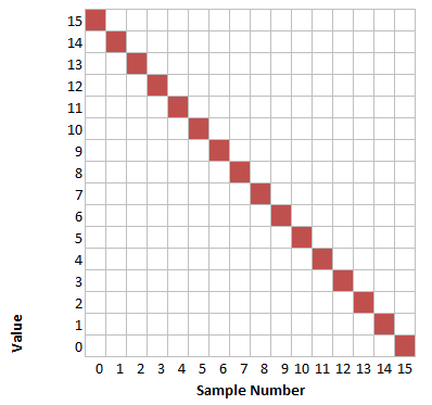
Of course, the real wave table is much larger, and holds values
from 0 to 4095. Each time a sample is requested, the accumulator
(which is an index into the wave table) is incremented using a
formula which divides up the wavetable to match the requested
frequency. Now, if you are requesting a frequency that perfectly
matches the wavetable, then you are all set. If, however, you
request a frequency that is, say twice as high as what's stored,
the samples come across like this:
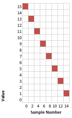
Similarly, if you wanted something at half the frequency, you
would end up hitting each sample number twice.
While not perfect (and definitely subject to issues with the Nyquist frequency and aliasing), this is good
enough for our purposes. Other options would be to pre-generate
different waveforms for different octaves, ensuring that no
harmonics above the Nyquist limit are present, such as Korg did with the DW series synthesizers. (I
had a Korg DW 8000 for a number of years after I traded in my Juno
106. Both were really fun synthesizers). That electric druid
article is great, btw, to learn how some of my favorite
synthesizers actually created their sound.
The code that accomplishes this is included in the
SawWavetableOscillator class.
using System;

using Microsoft.SPOT;


namespace NetduinoDacTest

{

    class SawWavetableOscillator

    {

        private const int _waveTableSize = 5000;

        ushort[] _waveTable = new ushort[_waveTableSize];


        private int _accumulator = 0;


        // this is temp. I'd pre-calc and store in future

        public void GenerateWaveTable()

        {

            int maxValue = 4095;


            double increment = (double)maxValue / _waveTableSize;


            for (int i = 0; i < _waveTableSize; i++)

            {

                _waveTable[i] = (ushort)(maxValue - increment * i);

            }

        }


        private int GetAccumulatorIncrementForFrequency(int sampleRate, double frequency)

        {

            return (int)(_waveTableSize / ((double)sampleRate / frequency));

        }


        private double _lastFrequency = 0;

        private int _lastIncrement = 0;

        private int _position = 0;

        public ushort GetNextSample(int sampleRate, double frequency)

        {

            // figure out position in table and return sample from there


            _position = _accumulator;


            if (_lastFrequency != frequency)

            {

                _lastFrequency = frequency;

                _lastIncrement = GetAccumulatorIncrementForFrequency(sampleRate, frequency);

                _accumulator += _lastIncrement;

            }

            else

            {

                _accumulator += _lastIncrement;

            }


            if (_accumulator > _waveTableSize)

                _accumulator = 0;


            return _waveTable[_position];


        }

    }

}
With a wavetable synth model, the oscillator is essentially
reduced to mapping the current position in the current frequency to
a point in the stored waveform.
In this example, I drive the oscillator from the main program,
using a single instance and requesting a single frequency.
The Main Program
The main program sets up the SPI channel, builds the wave table,
then loops creating samples as quickly as possible. The logic
for building the individual 16 bit messages, from the 12 bit sample
and 4 control bits, is included in the BuildSingleSpiMessage
function. The DAC selection code didn't work correctly, so I've
left it commented out.
using System;

using System.Threading;

using Microsoft.SPOT;

using Microsoft.SPOT.Hardware;

using SecretLabs.NETMF.Hardware;

using SecretLabs.NETMF.Hardware.Netduino;

using System.Diagnostics;


namespace NetduinoDacTest

{

    enum Dac

    {

        DacA = 0,

        DacB = 1

    }


    public class Program

    {

        private static int _sampleRate = 22500; //44100 or 48khz ideally 96khz would be gold

        private static int _channels = 1;       // mono


        public static void Main()

        {

            OutputPort ldacPin = new OutputPort(Pins.GPIO_PIN_D9, false);

            OutputPort shutdownPin = new OutputPort(Pins.GPIO_PIN_D8, true);


            SPI.Configuration config = new SPI.Configuration(

                Pins.GPIO_PIN_D10,  // chip select is D10

                false,              // active is low, according to DAC spec

                0,                  // setup time

                0,                  // hold time

                false,                                  // clock idle state is low

                true,                                   // data is sampled on rising clock edge

                (uint)(_sampleRate/1000 * 16 * _channels),  // clock rate in KHZ. 16 clocks * sample rate * # of channels

                SPI.SPI_module.SPI1);


            using (SPI dacSpi = new SPI(config))

            {

                // output samples

                ushort sample;


                double frequency = 440;       // a440


                // generate wave table for this frequency

                SawWavetableOscillator osc = new SawWavetableOscillator();

                osc.GenerateWaveTable();


                ushort[] messageArray = new ushort[1];


                while (true)

                {

                    sample = osc.GetNextSample(_sampleRate, frequency);


                    // need to set LDAC to high in case I wanted to output to both DACs at once (stereo)

                    //ldacPin.Write(true);


                    messageArray[0] = BuildSingleSpiMessage(sample, Dac.DacA);

                    dacSpi.Write(messageArray);


                    // need to set LDAC to low to allow output

                    //ldacPin.Write(false);

                }

            }

        }


        // assumes that the sample value provided is only 12 bits (0-4095)

        private static ushort BuildSingleSpiMessage(ushort sample, Dac selectedDac)

        {

            // bits 0-11 are sample

            ushort message = sample;


            // bit 12: output power down control. Set to 1 to allow output

            message |= 0x1000;


            // bit 13: output gain. We'll allow a set to 1 to have normal 1:1 output

            message |= 0x2000;


            // bit 14: Vref Buffer. We'll assume unbuffered, so zero

            message ^= 0x4000;


            // bit 15: dac A or Dac B. Zero is A, 1 is B.

            //if (selectedDac == Dac.DacA)

            //    message ^= 0x8000;

            //else

            //    message |= 0x8000;


            return message;


        }

    }

}
That's all there is to it. Once you understand the message
structure, the mechanics of communicating to the chip via SPI are
easy.
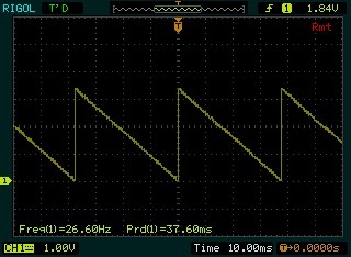
When run and hooked up to the scope, the output looks like
this:
(as an aside, I really dig that I can use UltraScope with my
hardware and capture screenshots etc. from the scope without
fiddling with a USB key or something)
That's a pretty good sawtooth, but the frequency is really low.
It maxes out at around 30-35hz at typical sample rates - far too
low to be usable for sound generation. Neat to look at, but doesn't
meet sound synthesis goals. I can up that if I greatly reduce the
sample rate to around 1-2khz, but that's just not reasonable for a
real app.
Realities
The sawtooth waveform generated had a pretty serious
zipper/motorboat effect due to not being able to generate samples
at the required rate. Much of the code was an attempt to try and
optimize (such as caching the last frequency and how I handled the
accumulator) rather than just raw code to generate a good waveform.
Note that I'm not sticking to a specific frequency here, as I
wasn't able to meet my base frequency requirements.
Normally, I'd use a stopwatch or something to keep the
sample output at a specific frequency. The better choice
here, is to set the SPI clock rate to 16 * _sampleRate * _channels
(or 16 * 44100 * 1 in the case of 44.1khz mono) and let the clock
handle timing for me. However, that's moot here as I can't keep a
minimum sample rate going in managed code.
Unlike the desktop and server versions of .NET, .NET
Micro Framework applications are interpreted, not
JIT-compiled. This means that .NET MF is going to be fine
for lots of things, but not really for generating thousands of
samples in real-time. After speaking with Chris from Netduino, he
suggested that I would be pushing the chip and the .NET MF
implementation way too hard in this project. He also suggested that
I could see a performance gain of almost 1000x+ if I were to
rewrite the critical sample generation (oscillator) and output code
in C++ and have it as a firmware extension.
As the oscillator code is not very complex, I may just do that.
Once Chris has the current firmware up on codeplex, I'll be able to
write some code using the .NET MF Porting Kit, and build my own
custom firmware builds, keeping in sync with the core Netduino
builds.
Conclusion and Next Steps
First, this was a TON of fun. I can't even begin to explain the
nerdgasm of seeing your hardware and source code output on an
oscilloscope. Whenever my code transcends the PC, I get pretty
excited (CNC is another example of this)
The Micro Framework will absolutely play an important part in
the synth project, but it won't be doing real-time sound
generation. Frankly, that's not what the MF is set up to do. Once I
get the Netduino firmware sources, I'll work on adding my own bits
to them. That will probably be a couple weeks. In the mean time,
back to WPF and Silverlight :)